Lisa/M v2.0

Lisa/M is a small, general purpose autopilot designed with flexibility across multiple applications in mind. Small weight and size, with (optional) integrated Aspirin IMU and full size 0.1" servo headers make the Lisa/M suitable for both fixed-wing and rotorcraft vehicles. This autopilot is based on a STM32 processor for extensive peripheral connection and faster processing.
A number of tutorials are being prepared for getting started with Lisa/M:
Please join us in our quest to make the getting started information even more, eh... informative, by adjusting those pages with your own improvements.
Features
Lisa/M is based on the 64 pins STM32F105RCT6 connectivity line family processor featuring 64k of RAM and 256k of FLASH. All the pins are exposed, providing access to the complete set of the STM32 peripherals. NOTE: This MCU is different from LISA/L. Lisa/L is based on the 64 pins STM32F103RE processor featuring 64k of RAM and 512k of FLASH, which is part of the high-density performance line family.
- STM32 microcontroller STM32F105RCT6 datasheet with 256kB flash and 64kB RAM
- Pressure sensor BMP085 (optional as of 08/2012)
- 7 x Analog input channels
- 3 x Generic digital in-/out-puts
- 2 x 3.3V TTL UART (5V tolerant)
- 8 x Servo PPM outputs (only 6 if second I2C (I2C1) bus in use)
- 1 x CAN bus
- 1 x SPI bus
- 1 x I2C bus (2 x when using only the first 6 Servo PPM outputs)
- 1 x Micro USB
- 4 x status LEDs with attached test point
- 10.8 grams (0.4 oz) (with Aspirin IMU mounted)
- 9.9 grams (0.35 oz) (without Aspirin IMU mounted)
- ~34mm x ~60mm x ~10mm
- 4 layers PCB design
With mounted Aspirin IMU has the following additional sensors on board:
- 3 Axis Gyroscope
- 3 Axis Accelerometer
- 3 Axis Magnetometer
- Barometer MS5611 (as of Aspirin v2.1)
NOTE: Lisa/M has pads for the BMP085 pressure sensor. Lias/M 2 boards made before August 2012 had the BMP085 sensor mounted. Boards made after August 2012 do not have the sensor mounted as they are designed to be used with Aspirin 2.1 which has the new MS5611-01BA03 barometric pressure sensor.
So, except for a GPS unit you have all necessary sensors for full attitude and altitude stabilization in an extremely small package.
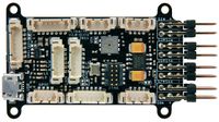
Lisa/M V2.0 top view
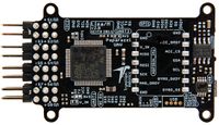
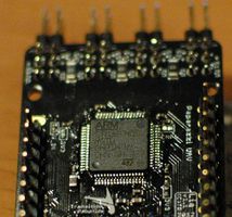
Lisa/M V2.0 bottom view

Pinout
Pins Name and Type are specified with respect to the Autopilot Board.


| Pin # | Name | Type | Description | Color |
|---|---|---|---|---|
| 1 | SERVOx | OUT | Servo signal (PWM)(See Note 1 below) | Yellow |
| 2 | SV | PWR | Servo Bus Voltage Rail (conf w/ JP1) | Red |
| 3 | GND | PWR | common ground | Black |
| Pin # | Name | Type | Description | Color |
|---|---|---|---|---|
| 1 | N/A | N/A | JTAG Debug Header (Pin 1 is +3V3) | None |
| Pin # | Name | Type | Description | Color |
|---|---|---|---|---|
| 1 | GND | PWR | common ground | Black |
| 2 | V_IN | PWR | UART Voltage (conf w/ JP6 and JP7) | Red |
| 3 | TX | OUT | USART3 Serial Output (3.3V level) | Yellow |
| 4 | RX | IN | USART3 Serial Input (3.3V level)(Pullup to Pin 2 voltage)(5V tolerant) | Orange |
| Pin # | Name | Type | Description | Color |
|---|---|---|---|---|
| 1 | GND | PWR | common ground | Black |
| 2 | +3V3 | PWR | 3.3V Rail from autopilot (conf w/ JP8 and JP9) | Red |
| 3 | RX1 | IN | USART1 Serial Input (3.3V level)(Pullup to Pin 2 voltage)(5V tolerant) | Orange |
| 4 | GND | PWR | common ground | Black |
| 5 | +3V3 | PWR | 3.3V Rail from autopilot (conf w/ JP8 and JP9) | Red |
| 6 | RX5 | IN | UART5 Serial Input (3.3V level)(Pullup to Pin 5 voltage)(5V tolerant) | Orange |
| Pin # | Name | Type | Description | Color |
|---|---|---|---|---|
| 1 | GND | PWR | common ground | Black |
| 2 | +3V3 | PWR | 3.3V Rail from autopilot | Red |
| 4 | PC12 | I/O | GPIO, connected to PC12 (5V tolerant) | Dark Tan |
| 5 | TRST | I/O | JTAG_TRST (also connected to LED1 cathode) | Light Tan |
| Pin # | Name | Type | Description | Color |
|---|---|---|---|---|
| 1 | GND | PWR | common ground | Black |
| 2 | +3V3 | PWR | 3.3V Rail from autopilot | Red |
| 3 | +5V | PWR | 5V Rail from autopilot | Red |
| 4 | ADC4 | I/O | by default connected to LED_4 cathode (Remove LED/resistor to use as ADC4) | Magenta |
| 5 | ADC6 | I/O | by default connected to LED_3 cathode (Remove LED/resistor to use as ADC6) | Pink |
| 6 | BOOT0 | I/O | BOOT0 | Grey |
| Pin # | Name | Type | Description | Color |
|---|---|---|---|---|
| 1 | N/A | N/A | USB (The USB connections are also available as 0.05" (1.27mm) through hole pads underneath the GPIO header) | None |
| Pin # | Name | Type | Description | Color |
|---|---|---|---|---|
| 1 | GND | PWR | common ground | Black |
| 2 | V_BATT | PWR | V_BATT Bus on autopilot, voltage divider for V_BAT_MEAS, (conf w/ JP2 to connect to V_IN) | Red |
| 3 | V_IN | PWR | Connected to autopilot voltage regulator inputs (conf w/ JP1, JP2 and JP3) | Red |
| 4 | CANL | I/O | CANL (5V level) | Orange |
| 5 | CANH | I/O | CANH (5V level) | Yellow |
| 6 | SCL | I/O | SCL (5V level)(See Note 1 below) | Green |
| 7 | SDA | I/O | SDA (5V level)(See Note 1 below) | Blue |
| Pin # | Name | Type | Description | Color |
|---|---|---|---|---|
| 1 | GND | PWR | common ground | Black |
| 2 | +3V3 | PWR | 3.3V Rail from autopilot | Red |
| 3 | MOSI | Out | MOSI | Orange |
| 4 | MISO | In | MISO | Yellow |
| 5 | SCK | Out | SCK | Green |
| 6 | SS | Out | SS | Blue |
| 7 | DRDY | I/O | DRDY | Dark Tan |
| Pin # | Name | Type | Description | Color |
|---|---|---|---|---|
| 1 | GND | PWR | common ground | Black |
| 2 | +3V3 | PWR | 3.3V Rail from autopilot | Red |
| 3 | +5V | PWR | 5V Rail from autopilot | Red |
| 4 | ADC1 | In | ADC1 (or LED_6 if populated) | Green |
| 5 | ADC2 | In | ADC2 (or LED_7 if populated) | Blue |
| 6 | ADC3 | In | ADC3 (or LED_8 if populated) | Light Tan |
| Pin # | Name | Type | Description | Color |
|---|---|---|---|---|
| 1 | GND | PWR | common ground | Black |
| 2 | +3V3 | PWR | UART Voltage (conf w/ JP4 and JP5) | Red |
| 3 | TX | OUT | USART2 Serial Output (3.3V level) | Yellow |
| 4 | RX | IN | USART2 Serial Input (3.3V level)(NOT 5V TOLERANT)(Pullup to Pin 2 voltage) | Orange |
| Pin # | Name | Type | Description | Color |
|---|---|---|---|---|
| 1 | GND | PWR | common ground | Black |
| 2 | +3V3 | PWR | 3.3V Rail from autopilot | Red |
| 3 | SCL | I/O | SCL (3.3V level) | Green |
| 4 | SDA | I/O | SDA (3.3V level) | Blue |
NOTE 1: SERVO7 and SERVO8 are directly connected to I2C1_SCL and I2C1_SDA lines. Therefore one has to choose, either use SERVO7 and SERVO8 OR have the I2C1 bus available, if that one needs to be used for whatever reason alongside the I2C2 bus. To use the servos 7 and 8 just set the <define name="USE_SERVOS_7AND8"/> in your airframe file and you are good to go. For this to work one must make sure to have the latest Paparazzi sourcecode.
LEDs
Lisa/M 2.0 has 5 LEDS (+1 power LED). There are 3 additional LEDs (LED_6, LED_7, LED_8) that are not populated by default (in favor of using ADC1-3 on the ANALOG1 connector). By default the LEDs are use for:
- LED_1, red
- SYS_TIME_LED: blinks with 1Hz
- LED_2, green
- AHRS_ALIGNER_LED: blinks until the AHRS is aligned (gyro bias initialized) and then stays on
- LED_3, green
- GPS_LED: blinking if trying to get a fix, on if 3D fix
- LED_4, red
- RADIO_CONTROL_LED: on if RC signal is ok
- LED_5, green
- not set to anything by default
Jumper Configuration
There are a number of jumpers on Lisa/M used to configure voltage levels and power input.
The default configuration is UART3 VCC at V_IN, UART1/2/5 VCC at +3V3, with the V_SERVO servo voltage rail NOT connected to the autopilot V_IN rail, allowing one to power the autopilot and servos separately. The +5V regulator is NOT bypassed, allowing a regulated +5V on listed headers and for the CAN transceiver and I2C level shifter. The V_BATT connector is NOT connected to V_IN, so one can attach a battery voltage to the V_BATT pin to measure the battery voltage, if so desired.
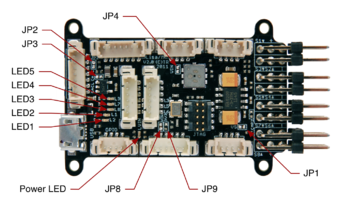
Lisa/M v2.0 Top Jumpers and LEDs
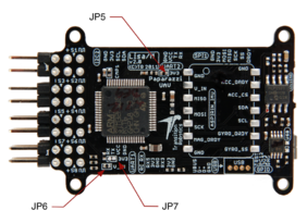
Lisa/M v2.0 Bottom Jumpers


| Jumper | Bus Connection | Default | Description |
|---|---|---|---|
| JP1 | SERVO_BUS to V_IN | OPEN | If closed then connects servo header voltage rail SERVO_BUS to autopilot input voltage V_IN rail |
| JP2 | V_BATT to V_IN | OPEN | If closed then connects I2C1/CAN rail V_BATT to autopilot input voltage V_IN rail |
| JP3 | V_IN to +5V | OPEN | If closed then connects autopilot input voltage V_IN rail to autopilot +5V rail, bypassing onboard 5V supply |
| Jumper | Bus Connection | Default | Description |
|---|---|---|---|
| JP6 | UART3_VCC to V_IN | CLOSED | Connects UART3 connector VCC to autopilot input voltage V_IN rail |
| JP7 | UART3_VCC to +3V3 | OPEN | If closed then connects UART3 connector VCC to autopilot +3V3 rail |
WARNING: UART3 GPS Connector is connected to V_IN, check your GPS input voltage before connecting!!!
WARNING: DO NOT CLOSE BOTH JP6 AND JP7 SIMULTANEOUSLY!!!
| Jumper | Bus Connection | Default | Description |
|---|---|---|---|
| JP4 | UART2_VCC to V_IN | OPEN | If closed then connects UART2 connector VCC to autopilot input voltage V_IN rail SEE WARNING BELOW |
| JP5 | UART2_VCC to +3V3 | CLOSED | If closed then connects UART2 connector VCC to autopilot +3V3 rail |
WARNING: UART2 RX is NOT 5V TOLERANT. Thus, while possible to connect UART2_VCC to V_IN, DO NOT ATTEMPT THIS. Only use JP5 (the default).
WARNING: DO NOT CLOSE BOTH JP4 AND JP5 SIMULTANEOUSLY!!!
| Jumper | Bus Connection | Default | Description |
|---|---|---|---|
| JP8 | UART1&5_VCC to V_IN | OPEN | If closed then connects UART1 and UART5 connector VCC to autopilot input voltage V_IN rail |
| JP9 | UART1&5_VCC to +3V3 | CLOSED | If closed then connects UART1 and UART5 connector VCC to autopilot +3V3 rail |
WARNING: DO NOT CLOSE BOTH JP8 AND JP9 SIMULTANEOUSLY!!!
There are additional jumpers on the board for expert or developer configurations, please see schematic and layout for more information.
Powering the Board
The 3.3V regulator on Lisa/M is a MIC5209-3.3YM capable of delivering up to 500mA. While it is possible to power this regulator with up to 16V, DO NOT do this. By default, the UART3 RX pin is pulled up to the input voltage V_IN. For this reason, 5V is the maximum input voltage. Note that the UART3 GPS Connector is connected to V_IN, check your GPS input voltage before connecting. If one desires to have V_IN at a higher voltage, the jumpers should be adjusted accordingly. As noted, this regulator can handle up to 16V, though experience has shown that this regulator can become very hot in operation with high input voltages, resulting in potential thermal shutdown while in flight. Depending on the expected current draw, it is best to power this regulator with a lower voltage. 5V is the perfect choice.
The onboard 5V regulator on Lisa/M is a LP2992, a low-noise, low-dropout linear regulator capable of delivering up to 250mA. This regulator can be bypassed with JP3, connecting the autopilot V_IN bus directly to the autopilot 5V bus if, for example, one is using an external 5V regulated supply, and a higher current is needed. Unless external use of 5V is required on the ANALOG1 and ANALOG2 headers, the only 5V usage onboard is for the CAN transceiver and the I2C1 level shifter.
When measuring the supply voltage of a battery with the V_BATT pin (could be connected to V_IN through JP2), it is important to note the maximum voltage limit. The voltage divider on the board for measuring with a 3.3V ADC is --V_BAT--/\/\10k/\/\--V_BAT_MEAS--/\/\2k2/\/\--GND--. This means that the maximum allowable voltage on V_BATT is

If a higher voltage measurement is desired, another voltage divider is required off-board. Alternatively, one could modify the existing voltage divider (e.g. change 10k resistor to 22k to get 33V maximum). When checking if voltage exceeds the maximum, make sure to consider maximum battery voltage, not nominal voltage (e.g. 4.22V or so for a single lithium cell, not 3.7V nominal, so the maximum number of cells in series is 3, like a 3S LiPo pack).
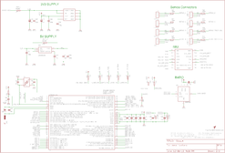
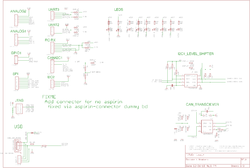
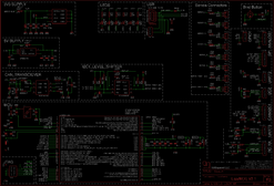
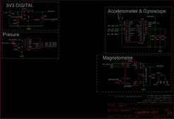
Schematic
LisaM V2.0 Schematic Sheet 1/3
LisaM V2.0 Schematic Sheet 2/3
LisaM V2.0 Schematic Sheet 3/3


Lisa/M V2.1 R3 Schematic Sheet 1/2
Lisa/M V2.1 R3 Schematic Sheet 1/2


Examples of Airborne Equipment Electrical Connections
Quadrocopter, Spektrum Satellite Receivers, PWM Motor Controllers (ESC) and dedicated avionics Battery Elimination Circuit (BEC)

This is a recommended powering configuration. It eliminates the balancing issues of the built in BECs into the ESCs.
The dotted lines from the BEC show the alternative wiring that does not require closing the VS jumper on the Lisa/M. The disadvantage is that you have to wire/crimp the BEC output wires into the picoblade molex connector providing the battery voltage reference. Usually it is easier to just use the existing "servo" connector on the BEC and closing the jumper instead.
Quadrocopter, Spektrum Satellite Receivers and PWM Motor Controllers (ESC)

This configuration assumes the ESCs have a battery eliminator circuit (BEC) function and provide 5 volts on their 5V pins. Closing JP1 powers Lisa/M and the attached accessories.
Warning: The built in BECs on the ESCs are usually linear voltage regulators, they are fairly inefficient compared to dedicated BECs that are usually implemented as switching DC/DC converters.
Warning: Due to manufacturing differences of BECs, connecting more then one BEC in parallel will likely cause one of the BECs to take majority of the load and dissipate most of the drop down voltage. (Read on how linear voltage regulators work.) As in this example the BECs are part of the ESCs, one of the ESCs will get warmer than the others, which in turn may lead to reliability issues.

Tip: To improve balancing between the ESC built in BECs you can add a 1Ohm resistor in the +5V line coming from the motor controller. This will cause some pre-loading of the voltage regulator and improve the load sharing between the BECs while decreasing the efficiency of the supply.
When using cheap ATMega or SiLabs-based PWM motor controllers consider replacing their firmware with either Simon Kirby or BLHeli firmware respectively to get useful performance of your multicopter! You can find a firmware compatibility list here.
Quadrocopter, Spektrum Satellite Receivers and I2C Motor Controllers (ESC)

This diagram "should" be the same for AscTec as well as Mikrokopter motor controller based airframes.
Fixedwing, Spektrum Satellite Receivers and Elevons Only

This configuration assumes the ESC has a BEC and provides 5 volts on its 5V pin. Closing JP1 powers Lisa/M and the attached accessories.
Fixedwing, Spektrum Satellite Receivers

This configuration assumes the ESC has a BEC and provides 5 volts on its 5V pin. Closing JP1 powers Lisa/M and the attached accessories.
Transitioning Quadshot Using Spektrum Receivers

The ESCs have BECs and provide 5 volts on their 5V pins. Closing JP1 powers Lisa/M and the attached accessories.
Still need: Large Fixed-wing with advanced power system and/or IC engine, PPM example
R/C Receivers
One can use Spektrum DSM2 or compatible receivers as well as traditional PPM receivers. It is even possible to connect two Spectrum or compatible satellite receivers for better redundancy or to improve RC signal reception. Connecting a RC receiver for flying your aircraft in manual mode during setup and test phase is 99% of the cases a must. Therefore the Paparazzi team made it easy to connect one.
Using a Spektrum DSM receiver
Physically connecting
Wiring up a Spektrum or compatible satellite receiver is not all to difficult to do. Note however that it is very important to make absolutely sure the connectors are properly made. Not being precise in this step can mean full RC loss and loss of airframe in the first tuning testflights.
A spektrum satellite receiver should be connected to the UART1 connector on the autopilot board. Make sure the voltage on the AP board UART1 + pin is not to high, or to low for your receiver.
Steps:
- Connect the minus(-) of the receiver to GND of UART1
- The receiver plus(+) to the UART1 Plus(+)
- Data out signal of the receiver to the RX pin on the UART1
Binding
To get a receiver and transmitter to work together you must perform a binding process.
It is important to bind your Spectrum DSM receiver to your transmitter via your Lisa board, not in any other way!
The way to bind is by temporary connecting via fiddly small molex pins. It is advised to make a small bind plug out of a molex connector for this purpose. Before you start make sure you have your airframe configuration already uploaded either via USB or a JTAG cable.
The bind procedure:
- On the connector ANALOG1 have a wire between the GND and ADC1 pin, located in the middle of the board
- Power up your autopilot board
- Hold the bind button on your transmitter, while keeping it pressed switch on your transmitter
- Wait...! All lights of the receiver blink and then go steady
- Let go of your transmitter bind button
- Power off your Lisa Board
- Remove the wire connecting the GND and ADC1 pins on the ANALOG1 connector
- Repower your board, if you have servos connected and wiggle the RC transmitter sticks some servos should move
That is all, you are done. The bind procedure only needs to be done once for your receiver.
Using a CPPM receiver
Using a CPPM receiver, a so called PPM sum stream input is possible. To make it work, you need a CPPM a.k.a. PPM sum, stream out capable receiver. Find out more following this link
Connecting
Connect the CPPM out signal to the RX pin of UART1.
Make sure put this in your airframe file in your AP target section.
  <firmware name="fixedwing">   <!-- or use "rotorcraft" -->
    ...
    <module name="radio_control" type="ppm">
        <configure name="RADIO_CONTROL_PPM_PIN" value="UART1_RX"/>
    </module>
    ...
  </firmware>
Alternative
However if in the case you want to use the UART1 port for something else, there is an option to connect the receiver to a servo pin. Yes, that's right, a servo connector is used for receiving a CPPM stream input. If you want to walk that path, the default pin number to capture the CPPM datastream is via servo connector SERVO6
If you connect the CPPM out capable receiver that way make sure to put this in your airframe file in your AP target section:
  <firmware name="fixedwing">   <!-- or use "rotorcraft" -->
    ...
    <module name="radio_control" type="ppm">
        <configure name="RADIO_CONTROL_PPM_PIN" value="SERVO6"/>
    </module>
    ...
  </firmware>
If you do not have or cannot modify a receiver to a CPPM out able receiver, a PPM encoder board can be used to avoid opening your receiver for PPM out modification. However with the very low prices of Spectrum DSMX CPPM out, lat time we looked you could have one starting from EUR 10,-
Using a S-Bus receiver
There is a third option, connect a receiver with S-Bus signal output. For this with regular Futaba receiver an inverter my be needed.
Extras
UART I/O
UART pins can also be used as general purpose I/O, this might come in handy in case all other inputs or your AP board are in use.
USB as UART1TX + hardware flow control

The USB_VBUS on the Lisa/M 2.0 can be used as UART1 TX. To do this, a diode has to be removed. Make sure to include a series resistor of 100-3000 Ohm to protect the microcontroller from overcurrents. The 2nd and 3th pin of the USB pads are CTS and RTS respectively. It is recommended to include a series resistor in the RTS line, as this is an outgoing line.
If you want to enable flow control in the software, but don't want to use flow control when no cable is connected to the CTS/RTS, a pulldown resistor of 10 kOhm has to be added between the CTS and the GND. If you do this, take care when connecting UART devices that have a large series resistor in their RTS line. The combination of the pulldown resistor and the series resistor might cause the high-level voltage to drop under the high-level threshold of the microcontroller, causing strange behaviour.
For Example the RTS , mostly a purple wire, is the pin 10 on the Xtend module when set in the module with Hardware flow control (use X-CTU) CTS, most blue, on pin 9 of the Xtend
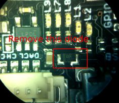
Remove this diode. After removing this diode you can not power the board via USB anymore.
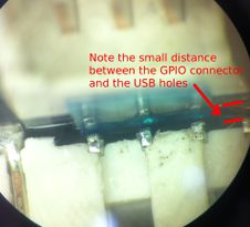
Take care of the small distance between the GPIO pins and the USB pads.


PCB
Gerber & Drill Files
Download Lisa/M v2.0 gerber & drill files (zip) Get the design
Assembly
To create and assemble a board oneself is possible. It takes some skills however.
For the Lisa/m v2.0 without the Aspirin sensor board a good soldering iron is enough.(smallest components are 0402) For the Aspirin Sensor board you need a hot air soldering station.
In case you wan to follow that path you need the design. You came to the right place here is the info to get the needed files;
Components Layout
Need some top and bottom of board images and line drawings here.
Bill Of Material
Download Lisa/M v2.0 Bill Of Material (zipped .xls file) Get the design
Open .sch File in Eagle, execute UPL --> bom.ulp , save as .txt
PCB and assembled boards suppliers
To difficult to create your own AP board, understandable, thus pre made board available via Get Hardware page... hopefully :)
Mechanical Dimensions

The overall height of the board including the servo connectors is 10mm. Note that the overall length includes the USB connector. The mounting holes are nominal 2mm diameter (with a bit of clearance). Beware that in version 2.1 of the Lisa/MX the mounting holes are for m3 screws.
Get the design
Source files
- download available on GitHub: Lisa/M v2.0 Cadsoft Eagle 6 Design
Gerber & Drill files
- download NOT YET AVAILABLE Need generated gerbers and drill files
Assembly files
- download NOT YET AVAILABLE Need Lisa/M v2.0 Components layouts (pdf)
- download NOT YET AVAILABLE Need Lisa/M v2.0 Bill Of Material
Uploading new software
New onboard software for the Lisa/M v2.0 can uploaded by connecting your PC via a micro-USB port to the autopilot board. For this the board need to contain the Luftboot bootloader. All Lisa/M 2.0 and Lisa/M 2.1 from 1BitSquared come with luftboot already in the board.
An alternative to get your firmware in the board is by using a Black Magic Probe JTAG/SWD debugger and programmer connected via the 10-pin JTAG/SWD Samtec connector that is on the board.
See the FirmwareFlashing page for an overview of different methods to upload new software to your autopilot.
Using luftboot
This is the default FLASH_MODE for Lisa/M v2.0 and v2.1, it could be explicitly selected by adding
<configure name="FLASH_MODE" value="DFU"/>
to the firmware section of your airframe file. Make sure to set Lisa/M 2.0 or 2.1 as it's target board.
Once USB is plugged in, the board automatically goes to bootloader mode and the status LEDs cycle up and down:

If you have trouble entering the bootloader mode or want to upload/update the bootloader itself, see the Luftboot page.
On Lisa/M V2.1 if you plug in the usb connector the board should go into bootloader mode automatically, older versions of the board come with a bootloader that has to be explicitly entered. If you have trouble with any part of the process, make a github account and click on the chat button in the lower right corner on this page.
Using JTAG
You still can use a JTAG adapter for flashing and debugging your paparazzi firmware. To use JTAG flashing configure the FLASH_MODE in your firmware section:
<configure name="FLASH_MODE" value="JTAG"/>
It is recommended to use the Black Magic Probe as your JTAG adapter. This avoids issues that result from using OpenOCD software. See more details here
Using JTAG will not overwrite the bootloader by default. To overwrite the luftboot bootloader configure
<configure name="NO_LUFTBOOT" value="1"/>
Then press upload as normal...
Serial Firmware Upload
Firmware upload using the factory integrated bootloader can be useful e.g. if you have overwritten Luftboot accidentally and don´t have access to JTAG.
Either set the flash mode in the target section of the airframe configuration:
<configure name="FLASH_MODE" value="SERIAL"/>
or add it to the commandline invocation:
make AIRCRAFT=<aircraftname> ap.upload FLASH_MODE=SERIAL
Due to hardware constraints, the board has to be modified to make use of the bootloader, which is only accessible on UART1:
- Diode D3 has to be removed (the bigger black brick next to the USB connector). Attention, no more powering via USB after that.
- BOOT1 has to be set to GND by connecting ACC_DRDY(unused) to GND at the Aspirin pads
Now a boot sequence works as follows:
- BOOT0 has to be set to 3.3V by use of a jumper cable
- Connect a 3.3V serial cable (FTDI, MAX232...) to UART1, the TX pin is USB_VBUS (accessible were the previously mentioned diode was located)
- Power the board and activate the bootloader program
Prevent board from going into bootloader mode
Normally, if you power up the board with the USB cable connected to a PC it will automatically go into bootloader mode. If you want the board to power up normally with the cable connected you can ground the ADC2 in the ANALOG1 connector.
Detailed Hardware Revision History
Changes Between LISA v1.1 and v2.0
- Lots of silkscreen improvements
- Added attributes to all parts to make the usage of bom-ex ulp possible.
- Improved routing to allow teardropping
- Fixed stm32f1, f2 and f4 compatibility circuit. (has to jump to ground not to 3v3)
- Connected existing UART RX pullups to the respective connector power pins instead of 3v3. To prevent connecting 5V over IO pin to the 3v3 power rail.
- Added pullups on all UART RX lines to prevent undesired floatation.
- LED's are connected to 3v3 now. To make sure we don't have an issue with voltage tolerance on the gpio pins.
- ...
Hardware Change Requests
If you have a Lisa/M 2.0 and in the process of using it you come up with something you find annoying, dangerous, or restricting, add your hardware update requests here. Better still, modify the Lisa schematics yourself and show your new improvements if you are skilled enough to do this.
- REQ: Replace BMP085 with MS5611 (the MS5611 seems to be better in performance then the BMP but it is more expensive and seems to be more difficult to obtain.
- A: Using a MS5611 is possible through using a Aspirin v2.1 board
- REQ: Replace 7 Pin CAN with molex with something less risky to be inserted in 7 Pin SPI in relation to powering the board via CAN molex.
- REQ: Separate spot for external power if powered via separate battery. Realizing we can via Servo ports by Bridge J1 but still like to measure board voltage then and have a way to add power without mistakenly insert I2CCAN Molex conector into SPI Molex on board connector. Thus a separate CAN and Power plug. Power on regular four pin molex with GND, V+5, , V_BATT, V_I (Current sense). Option to have thicker wire to be soldered to the board, for power hungry setups and other issues connectors for power are not a good idea.
- REQ: Replace Aspirin IMU board with InvenSense MPU-9150 and bring the MS5611 back onto the Lisa/M board to reduce footprint, mass, and manufacturing cost once the 9150 becomes readily available(if at al with SPI) and is tested to perform well.
Swap STM32 F1 for STM32 F4
A Lisa m v2 and a Lia autopilot can be easily converted to a much more powerful autopilot, We can swap the default STM32 F1 MCU for a STM32 F4 one. To be more specific, a STM32F405RGT6 chip [1]. A STM32F415RGT6 also works. The chip has the same dimensions (LQFP64 10x10mm package) with the exact same pinout as the original STM32F105RCT6 chip. The main advantages of the F4 chip are:
- 168MHz CPU speed, 1MB flash and 192kb RAM
- FPU (fast floating point computations)
- Configurable DMA streams so more peripherals can use DMA
- Multiplexed I/O pins so peripherals can be mapped to various I/O pins
- CPU usage only about 5% with standard rotorcraft flight configuration
STM32F405RGT6 chip can be ordered for example here.
HOW
- NEEDS: To replace the chip a good soldering station with microscope and enough light is recommended.
- NOTES: If you never done tings like this, better first practice de-solder skills on an old unused PCB from whatever electronic device, and old PC mainboard for example.
Steps:
- Removal of old MCU F1 chip is possible via various techniques. One way that works well and proven at least numerous times is to cut the pins where they enter the black MCU housing with a very sharp scalpel surgery knive.
- Remove the now lose old MCU
- Remove left over pins end stil on PCB by heating with soldeing iron tip and slide them inwards, static and a bit solder make sure they "stick" to your iron. Wipe of the pins from the tip e.g. via your copper wool sponge.
- Take a good tacky flux from tube and braid wire and with sliding solder iron and braid wire between iron and PCB carefully remove all solder from the solder pads on the PC. Remember: Flux is your friend!
- The small jumpers parts on CMP1 and CMP2 have to be removed so that they are open
- Now Re-solder your new F4 MCU, make sure the orientation is correct! Best to solder the first 2 opposite corner pins first to keep MCU in place while soldering other pins. If you are good, flux and drag soldering works ;)
That is it. Don't forget to change your boardtype in you old airframe file
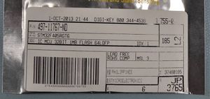
DigiKey part number for F4 chip
Lia F4 with the new chip


Flashing
The STM32F4 can be flashed via SWD/JTAG (e.g. with the BlackMagicProbe) or via DFU-UTIL. Luftboot currently supports only F1xx chips.
To program via DFU-UTIL:

First, install DFU-UTIL as shown here.
The two pairs of pins circled in red should be shorted (VERY CAREFULLY), eg with tweezers, as shown, i.e.:
1) The Boot0 and VDD pins on the STM32F4 should be shorted together.
2) The ACC_DRDY (Boot1) and GND pins should be shorted together on the Aspirin mounting pads. (This can be done even if an aspirin IMU is mounted).
The USB connector should then be plugged in. This action also powers the board. Do not connect any additional source of power.
Remove the shorts. The board should now be in bootloader mode. Only one green LED should be lit.
The board can then be flashed using DFU-UTIL.
Tested functional on a TRI Lisa/MX v2.0 using Paparazzi Master branch on 18 Nov 2014.
A guide how to flash the F4 chip from Eclipse can be found in RT_Paparazzi.