Umarim v1.0

The ENAC team has been working on long endurance airplanes for a while now. It appeared that one of the many limitations was the integration of the electronic part into the new fuselages which are becoming thinner and thinner. So we started to work on a new version of autopilot mainly based on the well-known tiny. The new sensors becoming smaller and smaller, we were able to integrate onto the board the IMU and a new design of barometer. So now, the ENAC team is proud to present you the UMARIM! (which means "I Hope" in turkish)
Hardware Revision History
| Version # | Release Date | Release Notes |
|---|---|---|
| v1.0 | 09/2011 | Initial release of Umarim |
Features
- NXP LPC2148 MCU based
- 1 x Triple axis Digital Gyroscope (Invensense ITG-3200)
- 1 x Triple axis Digital Accelerometer (Analog Devices ADXL345)
- 1 x Digital Baro-altimeter (Freescale MPXA6115 pressure sensor + Texas Instruments ADS1114 16bits ADC/PGA)
- 6 x Servo PWM outputs
- 1 x R/C receiver PPM frame input
- 2 x UART (TTL 3.3V, 5V tolerant)
- 2 x I2C bus
- 1 x SPI bus
- 1 x USB (client)
- 4 x General Purpose I/O or Analog input channels (0V - 3.3V)
- 5v / 1.5A switching power supply (input voltage range 5.5V min → 17.0v max)
- 3.3v / 1A linear regulator
- 2 x status LEDs
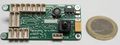
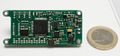
- 9 grams (0,32 oz)
- 56 x 25mm (2.2" x 0.98")
- 4 layers PCB design
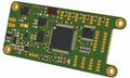
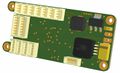
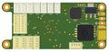
Umarim v1.0 3D bottom view
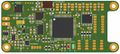
Umarim v1.0 3D top view
Umarim v1.0 top side
Umarim v1.0 bottom side


Pinout
Pins Name and Type are specified with respect to the Autopilot Board

| Pin # | Name | Type | Description | Color |
|---|---|---|---|---|
| 1 | GND | PWR | common ground | Black |
| 2 | +5V | PWR | 5V Rail from autopilot | Orange |
| 3 | SRVx | OUT | Servo signal (PWM) | White |
| Pin # | Name | Type | Description | Color |
|---|---|---|---|---|
| 1 | GND | PWR | common ground | Black |
| 2 | +5v | PWR | 5V Rail from autopilot | Orange |
| 3 | PPM_IN | IN | PPM Stream from R/C Receiver (5V tolerant) | White |
| Pin # | Name | Type | Description | Color |
|---|---|---|---|---|
| 1 | GND | PWR | common ground | Black |
| 2 | +3.3V | PWR | 3.3V Rail from autopilot | Red |
| 3 | SSEL1 | IN | SSP Slave Select. Selects the SSP interface as a slave (SSEL1) | Brown |
| 4 | MOSI1 | I/O | SPI1 Master Out Slave In. Data output from master / data input to slave | Grey |
| 5 | MISO1 | I/O | SPI1 Master In Slave Out. Data input to master / data output from slave | Green |
| 6 | DRDY1 | IN | External interrupt 0 input (EINT0) | Purple |
| 7 | SCK1 | I/O | SPI1 Serial clock. Clock output from master or input to slave | Yellow |
| Pin # | Name | Type | Description | Color |
|---|---|---|---|---|
| 1 | GND | PWR | common ground | Black |
| 2 | +5V | PWR | 5V Rail from autopilot | Orange |
| 3 | +3.3V | PWR | 3.3V Rail from autopilot | Red |
| 4 | AUX1 | I/O | General Purpose I/O #1 or ADC Input ADC_0 (lpc AD1.5) | |
| 5 | AUX2 | I/O | General Purpose I/O #2 or ADC Input ADC_1 (lpc AD1.4) | |
| 6 | AUX3 | I/O | General Purpose I/O #3 or ADC Input ADC_2 (lpc AD1.3) | |
| 7 | AUX4 | I/O | General Purpose I/O #4 or ADC Input ADC_3 (lpc AD1.2) |
| Pin # | Name | Type | Description | Color |
|---|---|---|---|---|
| 1 | GND | PWR | common ground | Black |
| 2 | +3.3V | PWR | 3.3V Rail from autopilot | Red |
| 3 | RXD0 | IN | UART0 Serial Input (3.3V level, 5V Tolerant) | Green |
| 4 | TXD0 | OUT | UART0 Serial Output (3.3V level) | Blue |
| Pin # | Name | Type | Description | Color |
|---|---|---|---|---|
| 1 | GND | PWR | common ground | Black |
| 2 | +3.3V | PWR | 3.3V Rail from autopilot | Red |
| 3 | RXD1 | IN | UART1 Serial Input (3.3V level, 5V Tolerant) | Green |
| 4 | TXD1 | OUT | UART1 Serial Output (3.3V level) | Blue |
| Pin # | Name | Type | Description | Color |
|---|---|---|---|---|
| 1 | GND | PWR | common ground | Black |
| 2 | +3.3V | PWR | 3.3V Rail from autopilot | Red |
| 3 | SDA0 | Open Drain I/O |
I2C0 bus Serial DAta | Brown |
| 4 | SCL0 | Open Drain I/O |
I2C0 bus Serial CLock | Blue |
| Pin # | Name | Type | Description | Color |
|---|---|---|---|---|
| 1 | GND | PWR | common ground | Black |
| 2 | +3.3V | PWR | 3.3V Rail from autopilot | Red |
| 3 | SDA1 BOOT |
Open Drain I/O |
I2C1 bus Serial DAta In-Circuit Serial Programming (ISP) enable (P0.14, +3.3v pullup) (Note) |
Brown |
| 4 | SCL1 | Open Drain I/O |
I2C1 bus Serial CLock | Blue |
Note: Holding this pin low for at least 3mS after a RESET (or power up) instructs the controller to enter programming mode.
| Pin # | Name | Type | Description | Color |
|---|---|---|---|---|
| 1 | GND | PWR | common ground | Black |
| 2 | USB+ | I/O | USB bidirectional D+ line | Green |
| 3 | USB- | I/O | USB bidirectional D- line | White |
| 4 | VBUS | IN | Indicates the presence of USB bus power (P0.23) (5V level) | Orange |
Schematic

Examples of Airborne Equipment Electrical Connections
Small Aircraft Connection Diagram

Large Aircraft Connection Diagram

PCB
Gerber & Drill Files
WARNING:
Umarim requires care during assembly of the ITG3200. While most are assembled fine (PPZUAV, ENAC, a few individuals have self assembled Umarim v1) The tolerances between the pad and the pins are quite close. During reflow the IC should center itself fine. However if it does not center it could connect the pad to a pin(s). Simplest way to avoid this is to use non conducting IC tape under the IC on the big square pad when doing self assembly.
PCB design Eurocircuits 6-C class compliant:
Download Umarim v1.0 gerber & drill files (zip)
RS274X, units = Inches, format = 2:5
- Umarim_v1-0_SILKSCREEN_TOP.GBR (Top Component Print Layer)
- Umarim_v1-0_SOLDERMASK_TOP.GBR (Top Solder Mask)
- Umarim_v1-0_SIGNAL_TOP.GBR (Top Copper Layer)
- Umarim_v1-0_INTERNAL_PLANE_1.GBR (Internal Copper Layer GND)
- Umarim_v1-0_INTERNAL_PLANE_2.GBR (Internal Copper Layer +3.3V)
- Umarim_v1-0_SIGNAL_BOTTOM.GBR (Bottom Copper Layer)
- Umarim_v1-0_SOLDERMASK_BOTTOM.GBR (Bottom Solder Mask)
- Umarim_v1-0_OUTLINE.GBR (Board Outline)
- Umarim_v1-0_DRILL.GBR (NC XY coordinates & Drill tools sizes)
Assembly
Components Layout
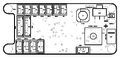
Umarim v1.0 bottom components Layout
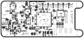
Umarim v1.0 top components Layout
Umarim v1.0 bottom components detail
Umarim v1.0 top components detail


Bill Of Material
Download Umarim v1.0 Bill Of Material (zipped .xls file)
| Qty | Manufacturer part number |
Part name / value | Designator | Description | Manufacturer | Package type |
Digikey part number |
Other distributor | |
|---|---|---|---|---|---|---|---|---|---|
| Resistors | |||||||||
| 2 | ERJ-3EKF33R0V | 33R | R16,R17 | 33.0 Ohm 1/10W 1% | Panasonic - ECG | 0603 | P33.0HCT-ND | ||
| 1 | ERJ-3EKF1000V | 100R | R14 | 100 Ohm 1/10W 1% | Panasonic - ECG | 0603 | P100HCT-ND | ||
| 2 | ERJ-3EKF3900V | 390R | R12,R13 | 390 Ohm 1/10W 1% | Panasonic - ECG | 0603 | P390HCT-ND | ||
| 2 | ERJ-3EKF1501V | 1.5K | R11,R15 | 1.50K Ohm 1/10W 1% | Panasonic - ECG | 0603 | P1.50KHCT-ND | ||
| 1 | ERJ-3EKF1801V | 1.8K | R18 | 1.80K Ohm 1/10W 1% | Panasonic - ECG | 0603 | P1.80KHCT-ND | ||
| 4 | ERJ-3EKF2201V | 2.2k | R5-R8 | 2.20K Ohm 1/10W 1% | Panasonic - ECG | 0603 | P2.20KHCT-ND | ||
| 1 | ERJ-3EKF3301V | 3.3K | R19 | 3.30K Ohm 1/10W 1% | Panasonic - ECG | 0603 | P3.30KHCT-ND | ||
| 5 | ERJ-3EKF1002V | 10K | R1-R3,R9,R10 | 10.0K Ohm 1/10W 1% | Panasonic - ECG | 0603 | P10.0KHCT-ND | ||
| 1 | ERJ-3EKF2203V | 220K | R4 | 220K Ohm 1/10W 1% | Panasonic - ECG | 0603 | P220KHCT-ND | ||
| Capacitors | |||||||||
| 2 | C1608C0G1H180J | 18p | C33,C34 | Ceramic 18pF 50V C0G 5% | TDK Corp. | 0603 | 445-1272-1-ND | ||
| 1 | C1608X7R1H222K | 2.2n/50V | C32 | Ceramic 2.2nF 50V X7R 10% | TDK Corp. | 0603 | 445-1309-1-ND | ||
| 1 | C1608X7R1H103K | 10n | C31 | Ceramic 10nF 50V X7R 10% | TDK Corp. | 0603 | 445-1311-1-ND | ||
| 24 | CC0603KRX7R8BB104 | 100n | C1-C9,C14-C27,C35 | Ceramic 0.1uF 25V X7R 10% | Yageo | 0603 | 311-1341-1-ND | ||
| 4 | C1608X5R1E105K | 1u/25V/X5R | C11,C12,C29,C36 | Ceramic 1.0uF 25V X5R10% | TDK Corp. | 0603 | 445-5146-1-ND | ||
| 1 | C1608X5R0J106M | 10u/6.3V | C30 | Ceramic 10uF 6.3V X5R 20% | TDK Corp. | 0603 | 445-4112-1-ND | ||
| 2 | TAJA336K006RNJ | 33u/6.3v | C13,C28 | Tantalum 33uF 6.3V 10% | AVX Corp. | A case (EIA 3216-18) | 478-1666-1-ND | ||
| 1 | TR3D107K020C0080 | 100u/20V | C10 | Tantalum 100uF 20V 10% | Vishay/Sprague | D case (EIA 7343-31) | 718-1774-1-ND | ||
| Inductors | |||||||||
| 1 | B82462G4682M | 6.8u | L1 | 1.65A Power Inductor | Epcos Inc. | 6.0x6.0 mm | 495-1999-1-ND | ||
| Semiconductors | |||||||||
| 1 | MPXH6115AC6U | MPXH6115AC6U | IC1 | Integrated Silicon Pressure Sensor | Freescale Semicond. | 1317A-03 | MPXH6115AC6U-ND | ||
| 1 | ADS1114IRUGT | ADS1114RUG | IC2 | 16-BIT I2C Analog-to-Digital Converter | Texas Instruments | X2QFN10 | 296-24933-1-ND | ||
| 1 | PCA9306DCUR | PCA9306DCU | IC3 | Dual Bidirectional I2C Voltage-Level Translator | Texas Instruments | VSSOP8 | 296-17988-1-ND | ||
| 1 | TPS62112RSAT | TPS62112 | IC4 | 17V, 1.5-A, Synchronous Step-Down Converter | Texas Instruments | QFN16 | 296-19717-1-ND | ||
| 1 | LM3940IMP-3.3/NOPB | LM3940IMP-3.3 | IC5 | 1A low dropout regulator for 5V to 3.3V conversion | National Semicond. | SOT223 | LM3940IMP-3.3CT-ND | ||
| 1 | LT6654BHS6-3.3#TRMPBF | LT6654BHS6-3.3 | IC6 | 3.3V Precision Voltage Reference | Linear Technology | SOT23-6 | LT6654BHS6-3.3#TRMPBFCT-ND | ||
| 1 | ADXL345BCCZ-RL | ADXL345 | IC7 | 3-Axis 16 g Digital Accelerometer | Analog Devices Inc. | LGA14 | ADXL345BCCZ-RLCT-ND | ||
| 1 | LPC2148FBD64,151 | LPC2148FBD64 | IC8 | Single-chip ARM7 32-bit microcontroller | NXP Semicond. | LQFP64 | 568-1765-ND | ||
| 1 | ITG-3200 | ITG-3200 | IC9 | 3-Axis Digital-Output Gyroscope | InvenSense | QFN24 | N/A | Farnell(#1858279)
Sparkfun(#SEN-09793)" | |
| 1 | CD4017BPWR | 4017 | IC10 | Decade Counter/Divider with 10 Decoded Outputs | Texas Instruments | TSSOP16 | 296-14252-1-ND | ||
| 1 | LT6656BCS6-5#TRMPBF | LT6656S6-5 | IC11 | 5V Precision Voltage Reference | Linear Technology | SOT23-6 | LT6656BCS6-5#TRMPBFCT-ND | ||
| 1 | APT1608SURCK | KP-1608SURC | LED1 | SMD Chip Red LED Lamp | Kingbright Corp. | 0603 | 754-1123-1-ND | ||
| 1 | APT1608MGC | KP-1608MGC | LED2 | SMD Chip Green LED Lamp | Kingbright Corp. | 0603 | 754-1118-1-ND | ||
| 1 | DTA143ZE-TP | DTA143ZE | T1 | PNP Pre-Biased Small Signal Transistor | Micro Commercial Co. | SOT523 | DTA143ZE-TPMSCT-ND | ||
| Connectors | |||||||||
| 7 | 53047-0310 | RC,SRV0-3,SRV6-7 | J3,J8-J13 | Picoblade 3 pins 1.25mm straight header | Molex Inc. | - | WM1732-ND | ||
| 5 | 53047-0410 | UART0-1,USB | J2,J5-J7,J14 | Picoblade 4 pins 1.25mm straight header | Molex Inc. | - | WM1733-ND | ||
| 2 | 53047-0710 | SPI1,AUX | J4,J15 | Picoblade 7 pins 1.25mm straight header | Molex Inc. | - | WM1736-ND | ||
| Other | |||||||||
| 1 | CX5032GB12000H0PESZZ | CX5032GB12000 | Q1 | CRYSTAL 12.0MHZ 12PF SMD | AVX Corp. | 5.0x3.2mm | 478-4359-1-ND | ||
PCB and assembled boards suppliers
Hopefully, available soon on Get Hardware page :)
Mechanical Dimensions

Downloads
WARNING: THERE IS AN ERROR IN THESE GERBER FILES!
The footprint of the ITG3200 extends below the base of the IC. Because the IC has a metal baseplate, this causes a 0.025mm tolerance on placement of the ITG-3200 which is almost impossible to achieve. I an unable to correct the files because I don't have Protel.
Source files
Gerber & Drill files
Assembly files
Paparazzi USB Bootloader Upload
Required components
- 1 x FTDI TTL-232R-3V3 (Digikey #768-1015-ND) USB to UART converter cable with +3.3V TTL level UART signals. (see Note 1)
- 2 x 4-pin connector housing Molex Picoblade 51021-0400 (Digikey #WM1722-ND)
- 5 x crimp terminal female Molex Picoblade 50058-8000 (Digikey #WM1775CT-ND)
- 1 x 6-pin 0.1" pitch single in line male connector header Samtec TSW-132-07-TS (Digikey #SAM1035-32-ND) or equivalent
- 28-32AWG wiring cable
- Note1: It is advised to use FTDI USB-serial converter, as serial FTDI chips are by default working well in Linux.
- The Paparazzi ground station software is configured to look for modems on FTDI ports by default.
- This harness can also serve as a modem interface (after it's use in Bootloader uploading) if you plug it on Umarim's UART1 connector
Connection Diagram
Make up a wiring harness similar to the following

Boot Sequence
