RC Receivers and Radios
Introduction
To be able to test your airframe before it flies fully autonomous a regular RC transmitter in combination with a receiver can be used. This is essential for testing and tuning your airframe. For this to work the received steering commands have to leave the receiver. Only then with this flow of command data the autopilot when flown in manual mode can do something you tell it to. This page is to give you information of how to connect various receivers. Also how to modify receiver so they can talk to the autopilot.
Setup
Once you have physically connected your receiver we need to setup the transmitter and receiver combination correctly. This can be an complex task due to the overwhelming amount of options. To assist you in this setup quest a specific wiki page is available to help you out.
If you have a new Graupner HOTT system, the Graupner HOTT setup page will provide all key information about setting up the Graupner transmitter and receiverand correctly output a ppm sum stream.
2.4GHz Receivers
There are three output type in use which you can connect a 2.4GHz receiver to your autopilot board:
- CPPM, where the C stands for Combined, the PPM sum stream output, supported on all current autopilot boards,
- Spektrum serial data output
- S-BUS data output
If you come across the term "Satellite Receiver", it has nothing to do with satellites in earth orbit. It is just a term to describe an auxiliary receiver normally used to improve reception by plugging into the 'main' receiver.
If your receiver can not output one of the signals above, maybe you need following:
- Must have combined PPM pulsetrain out or use PPM Encoder board. See the Get Hardware page for links to suppliers)
- At least one extra channel beyond those needed to control the servos and motor. (throttle-roll-pitch-mode)
HOTT
CPPM output
Graupner GR-12/GR-16/GR-20 HOTT
GR-12/GR-16/GR-20 are Transmitters from the Graupner HOTT Series.
- 2.4 GHz FHSS system
- regular software updates, good support
- different languages (also with voice output)
- receivers work with 3.6 V to 8.4 V (functional down to 2.5 V)
- highly adjustable
For a detailed instructions for updates and setup look at the Graupner_HOTT_setup page.
Spektrum
The wildly popular Spektrum and other brands of receivers using the spectrum protocol are widely available. Below a few of the tested ones. It is very likly others will also work well with Paparazzi, the only diffrence is, we did not thest them yet. Best of all the protocol is well reverse engineered and almost all details are known and implemented in various opensource libraries.
The connector used in the Spektrum Sat receivers is JST part number S3B0ZR(LF)(SN) (Digikey part 455016700ND). This mates to part JST ZHR03 (Digikey 455011600ND). On the autopilot side various connector can be expected. On the Lisa type of board, Molex Picoblade.
DSM2 v.s. DSMX
If you have no specific reason, use DSMX equipment. DSMX is more robust against interference and advised over DSM2 receivers. This very good article explains it all in depth. We could not have explained it better ourselves.
CPPM output
A nice solution for e.g. Tiny and TWOG autopilot boards is use modern DSM and your trusty based autopilot board with the CPPM inputoption. This works as well on LPC and STM based boards. Note that for a configuration radio file on should choose an own one not spektrum regardless that the connection is over DSM the pulses are PPM out not the serial DSM.
OrangeRx R410X

OrangeRx R410X DSMX compatible 4Ch with 6 Channels PWM/CPPM out. This is the prefered modern alternative if you are looking to replace your "Classic" 35/36/40/41/72mHz receivers PWM/CPPM out for a robust DSMX receiver at almost no cost. Last time we looked the receivers where sold for about 8 Euro (~ 10 USD)
In order to use the receiver, failsafe has to be deactivated so the AP can detect the loss of signal (the rx still outputs PPM-frames if you don't). To deactivate it you have to give full thottle and also give full trim. Then you have to (re-)bind the rx. Check carefully if the GCS displays NONE if you switch of the tx.
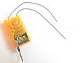
OrangeRx R615X

Another option is to use the OrangeRx R615X 6Ch 2.4GHz Receiver with CPPM out.
DT RX31c
A Deltang, with software v3.5 also DSMX support, so small it is sure worth mentioning:

- Outputs combined PPM (Sum PPM),7 channels for e.g. a Spektrum DX8 and DX6 transmitter
- Subminiature receiver with full range. Only 0.21 grams!. Cost about EUR 30.
- The solution for very tiny aircraft.
- The channels order with Spectrum DX8 in acro mode: Throttle, Roll,Pitch, Gear, Mix, Flap,Aux2
This manufacturer has more interesting receivers, worth a look
Direct serial output
OrangeRx R110X
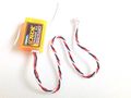
Orange DSMX small receiver
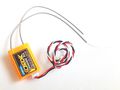
Orange DSMX small receiver with longer antenna


OrangeRx R110X Satellite DSMX Receiver R110X. Works well, simple to connect. Although called, "Satellite Receiver" it is usable as a ful blown receiver when connected to an AP board. There is also a version with long antenna with two U.FL connectors on the PCB.
Spektrum 9645

Spektrum 9645 satellite receiver. Works well, simple to connect. the DSMX mode is not used, it is used in the DSM2 mode, the receiver is backards compatible with that protocol.
S-Bus output Spektrum
Although drafted up by Futaba there are lots of receivers from other brands also giving S-Bus signal output. Paparazzi is perfectly capable to decode the S-Bus information from whatever receiver and use it. It can be useful when you have no Spektum RX in connection on your autopilot board, in that case a solution could be to use a Spektrum receiver which outputs a s-Bus datastream.
Orange DSMX 3C 14ch with S-Bus output
If you need a tiny DSMX receiver with SBus out to connect directly to your autopilot, a good option is to use this one

Orange DSMX 8C 14ch with S-Bus output
For more reception redundancy, one can add a satellite receiver like the RX110XL, and still have SBus output
Orange DSMX 8 with 14CH SBus output
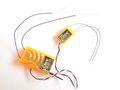
Orange DSMX and a satellite


FASST
Futaba FASST, Robust receivers. Read more about the FASST system here.
CPPM output
Futaba FASST 7-channel receiver

- Pin 8 (upper right corner in picture) of the small IC on the right contains 5 PPM pulses and can go directly to paparazzi. Pulse 6 and 7 go directly to the servos.
- Best is to remove the resistors of one of the channels and connect a small wire to pin 8 to get the combined 5 pulses on the robust 1/10th inch header.
- Do not forget to use channel 3 (only failsafe channel) as mode switch with fail safe "throttle off" as mode 2.
Robbe RASST 7 & 8 channel receivers
Robbe has produced line of Futaba FASST compatible receivers that can output only PPM which results ablility to plug into autopilot without encoder.
- R6007SP 2,4 GHz RASST - 7 channel, for small aircraft
- R6107SP 2,4 GHz RASST - 7 channel, >1000m range
- R6008SP 2,4 GHz RASST - 8 channel, upto 3000m range
Switch Assignment
To assign the three position switch to any other channel but channel 7 follow these steps:
- Set up aux2(refers to aux2 on rx not the switch on the tx. aka ch7) with its input selected as 3 pos switch.
- Set up this mix - Gear to Gear (Up=-100, Down=-100, Offset =0). This inhibits the gear switch.
- Set up another mix - Aux2 to Gear (Up=100, Down=100, Offset = 0).
Notes:
- Gear on a DX-7 Air is Channel 5 and AUX2 is CH7. Once again i am referring to the inputs which are labeled on the RX not what the switches are named on the TX. If your using a DX-7 heli please substitute the names for what the rx channels are named into this guide
- DX7 Heli the 3-pos switch is named "flight mode"
- DX7 Air the 3-pos switch is named "flaps"
Failsafe Setup
To set up the mode channel (3 pos switch) to default to auto2 if connection is lost between rx and tx follow these steps:
- Put 3 position Switch into AUTO2 Position
- Put in bind plug
- Power up
- REMOVE the bind plug
- Power up Tx while pushing bind button
- Wait until light becomes steady and not blinking (it may become steady right off but will then start blinking again so let it go at least 5 seconds)
S.bus output
S.bus to CPPM
Frsky has an SBUS to CPPM converter which can be used with S.bus receiver e.g. R6303SB
Failsafe
To properly get the LOST bit when the S.bus receiver is out of range a hack for lpc21 is to use the led signal of the receiver (if the color is changed/tuned off when the signal is lost) and put this to a GPIO input. Then define some parameters to turn this into RC_LOST signal.
See sw/airborne/arch/lpc21/subsystems/radio_control/ppm_arch.h:54 And for the airframe (for pin P0.17):
| File: conf/airframes/myplane.xml |
    <subsystem name="radio_control" type="ppm">
      <define name="USE_PPM_RSSI_GPIO"/>
      <define name="PPM_RSSI_IOPIN" value="IO0PIN"/>
      <define name="PPM_RSSI_PIN" value="17"/>
      <define name="PPM_RSSI_VALID_LEVEL" value="0"/>
    </subsystem>
|
MULTIPLEX
CPPM output
Jeti Duplex 2.4 GHz Receiver Rsat 2

- Outputs PPM, no soldering or PPM board required
- Only 12 gramms
- Full duplex technology provides safe radio link and redundant telemetry to standard paparazzi telemetry.
- Transmitter module can be installed in any receiver.
More information can be found a the Homepage of Jeti and the MikroKopter Wiki.
PCM Receivers
Most of the known PCM transmitter also can be set to PPM mode. If this is set, then the regular description for PPM applies since the PCM receiver like a JR/Gaupner SMC16 Scan can output PPM perfectly.
However if setting up you transmitter to PPM out then the following applies:
- Must use ppm encoder board. (See Get Hardware page for suppliers)
- At least one extra channel beyond those needed to control the servos and motor.
PPM Receivers
To use a 26/27/35/40/41/72/ MHz receiver a few requirements are necessary
- At least one extra channel beyond those needed to control the servos and motor.
- A receiver or modified receiver which outputs a full ppm signal.
R/C Receiver Interface
All versions of the Paparazzi autopilot include a connector to interface with a standard R/C receiver for manual or semi-autonomous control during the testing and tuning phases. Two interface options exist:
- Tap into the PPM signal running between the RF section and the servo driver of your receiver and route it to the Paparazzi. Let the Paparazzi generate individual servo signals and connect all servos directly to the autopilot. This method requires only 3 wires to the receiver (power and PPM), is compatible with all Paparazzi autopilots, and provides 8 manual R/C channels and the potential for more autonomous channels regardless of the capability of the R/C receiver.
- Cut the PPM trace and route it thru the autopilot and back to the receiver, using the servo driver IC on your R/C receiver to drive the servos. This option requires 4 wires (Ground, PPM-in, PPM-out, Reset) and your receiver must have a supported servo driver IC. This allows you to use the large servo connectors on your R/C receiver and does not require any modification to your servos or ESC but does require you to cut a trace on your R/C receiver and limits the number of servos to the capacity of your receiver. Compatible with Classix and Tiny 1.1.
- Note that on the Classix the PPM_in pin is FOO2...
Note 1: Exact value not critical. Depending on RC Transmitter type & Manufacturer.
Note 2: Depending on Transmitter number of Channels and t,,n,, durations.
Note 3: Not critical. Depending on Synchro detection method.]]
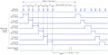
PPM Timing Diagram
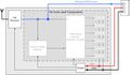
3-Wire setup, driving servos from the autopilot
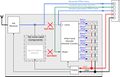
4-Wire setup, driving servos from the R/C receiver


Common demux chips
Typical used chips are the cmos 4015 and 4017.
The 4015 uses either pin 1 or pin 9 for the clock and the input is on 7 and 15. The 4017 has just one shift register and has its clock input on pin 14 and the enable on pint 13.
In most receivers you are after the clock; though some may be pulsed; in which case you need the enable. Note that the 4017 enable has inverted logic (low to be enabled) whereas the input on the 4015 can be either (typically high). If the enable pin is held low (4017) or if the input pin (4015) is held high always;e.g. connected to the ground or the Vcc - then it is fair to assume that the PPM signal is most propably on the clock input.
35/40Mhz RC Receivers
Note that there is information on modifying other receiver models at mikrokopter.de. It's in German however the pictures contain most of the information or use google translate. Shielded wire is recommended for receiver and autopilot connection, as unshielded one may cause noise in receiver.
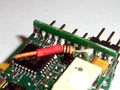
Futaba FP-R116FB 6 Channel FM 35MHz receiver

- Orange wire is connected to PPM signal
- Red wire is connected to VCC
- Brown wire is connected to GND
Futaba R136F 6 Channel FM receiver

- 41 MHz
- White wire is connected to PPM signal
Futaba R168DF 8 Channel dual FM receiver

- 35 MHz
- PPM wire is connected to 862 receiver pin on the board. VCC and GND is on the 8/B original position.
ACT Micro-6 FM receiver

- Available in 35 or 40 MHz versions
- White wire is connected to PPM signal
- Datasheet (German)
ACT DSL-4top mikrokopter.de version

- Special version for mikrokopter.de - Only available in their shop!
- Outputs PPM directly on the channel 1 connector!
- No soldering necessary
- ACT Lifetime warranty
- Sells for ~45 euro
Futaba R115F 5 Channel FM receiver

- Available in 35 and 40 MHz versions
- White wire is connected to PPM signal
JETI REX 5 plus (no MPD) receiver

- Popular Czech made micro r/c receiver, available in 35 or 40 MHz versions
- ´folded´ PCB design with parts inside, mostly inaccessable
- Small grey wire is connected to via with PPM signal
- Unusual connector used for testing, soldering recommended
- shielded wire recommended, this one taken from PC parts recycling (former soundcard to m/b connector cable)
- Datasheet (English)

Receiver RX-7-SYNTH IPD receiver Multiplex-rc.de

- Available in 35, 36 and 40 MHz versions
- A compact, high-quality 7-channel single-conversion FM / PPM IPD receiver
- Easy modification through connectors, see pictures
Protech 5FM 35 mHz Receiver
The low cost Protech '5FM' receiver makes use of an SMD version of the standard 74AHC164[1] 8 bit shift register; you are after PIN 1 of this chip. The circuit board has a testpad for just this pin at the top side of the circuit board.
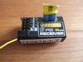
Figure 1.
Protech 5FM 35 mHZ Receiver, mark 2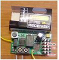
Figure 2.
PPM tap location for the Protech 5FM receiver, near the 74AHC164 shift register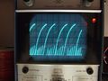
Figure 3.
Protech 5FM PPM signal - not very clean/digital


Two physical versions exist; the older one [2] and a newer one pictured (fig 1). It has been distributed by protech with various ready-to-fly planes; such as the Skyraider[3].
The solder/testpad you are after the one right next the 74x164 chip its pin 1. In this image it has a jellow wire soldered to it (the yellow wire at the top left is the normal antenna connector (fig 2). Note however that the signal is not very clean (1v/div) - which may cause issues - as shown in the above image (fig 3).
This is further compunded by the relatively noisy electrical engines; which are not brushless. A ferrite coil does not seem to help enough - Papparazi and GPS loose sync often through Xbee. Replacing the engine by a brushless outrunnen resolve the issue completely.
Profi Penta 35 MHz


Graupner R16Scan
The Graupner R16Scan and SMC16Scan are available in 35,36,40,41Mhz versions and belongs to one of the most reliable traditional receivers in it's class. It's a highly selective PLL SCAN narrow-band FM superhet receiver. Has 8 servo connections. And the best thing; No crystals swap is required with this receiver since it scans for your TX transmission frequency. Modified for PPM output, it can output 9 separate channels.
To modify this receiver for use with an autopilot some soldering on tiny IC pins is needed. No additional electronic parts needed.
- Desolder existing resistor from IC pin, fast and carefully
- solder a short wire to the pin on the other side of the IC as on the picture, preferably als put some isolation over it
- Solder this wire to the resistor, move isolation over resistor
- Use a little UHU por glue to make sure nothing moves when flying in rought conditions
The PPM combined data is now available on connector 8. You still can power the receiver seperatly via + - pins if you want to. Or straight from the AP board 5v out.
How to modify
Modification from other side
Modification Closeup
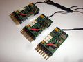
Well... why not change them all in one go.


72Mhz Receivers
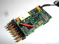
Castle Creations Berg 4L

- Expect fantastic performance from these $40 USD parts but be warned that they are known to have unreliable crystal sockets and brittle antenna wire. The Berg 7 channel receiver should work equally well and is known to have a better crystal socket - note that either receiver will provide 8 channels in manual R/C mode when used with Paparazzi. Note: the rugged Berg 4 cannot be modified, only the Berg 4L and Berg 7.
To Modify a Berg4L, follow these instructions:
- Remove the shrink wrap. Use a good knife and be careful to not damage any of the components on the receiver. I would recommend that you cut on the sides (edge of the PCB) to be sure to avoid damaging the shielding
- Desolder the headers. We will not use them with tiny AP as the servos are connected directly to the AP. This is pretty easy to do when you have a hot air rework station. If you don't have one, your best bet is to cut the header off and remove the left over pins one by one with a regular iron. There is a piece of shielding material that is connected to one of the ground pins of the header. You need to remove it carefully from the header without damaging it and re-solder it to the gnd pad.
- You need to solder 3 wires to the receiver. Gnd, +5V and PPM. To locate the PPM signal, first locate the PIC micro controller close to the location of the headers. The PPM signal is on the corner pin closest to the corner of the receiver. Soldering a 28guage wire directly to the PIN isn't very difficult. For the power connection, use the pads that were used for the header. The outside pin is Gnd, the second pin is +5V. What I did is solder the wires on the pad going straight down, then I looped the 3 wires 360 degrees and glued them to the PCB with hot glue. This provides good strain relief.
- While you have the PCB in your hands, take the opportunity to remove the crystal connector and solder your crystal directly to the PCB for added reliability.
- I also used some hot glue to add more strain relief to the antenna
- Use some large shrink wrap to cover the entire receiver again
Hitec Electron 6 72MHz Reciever
This was written for MNAV from crossbow but is still usable with PPRZ.

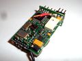
Corona Synthesized Dual-Conv Receiver 8Ch
This receiver is available in 27,35,36,40,72 mhz and a Synthesized receiver, meaning you do not need to change frequency crystals.
How to modify for combined signal
- Cut the 8th channel PWM output pin near the PCB.
- Connected a pin from the Atmel (see picture) to the 8th channel PWM signal. (optionally, weaving the wire through some holes on the board.) Make sure you have a fine tip on your soldering iron and a magnifying glass strapped to your head!
- Glue the wire down (CA works)
- Be sure to glue the pin that you cut in place (previously, being soldered to the board was holding the pin in place)
It is maybe possible to reprogram the atmel with your own firmware. If you succeed in this plz add relevant info here.
That pin provides a 1V to 2V signal, it works with the PPRZ, although its a bit gittery (the slew rate is not real good).


UHF Receivers
Note that in most countries an amateur radio license is required to use 433MHz UHF.
See also Modems#HAM_.2F_CEPT_Licence.
Scherrer UHF

The Scherrer UHF is a high quality diversity radio control system. It has a PPM output and can be connected directely to Paparazzi. A ppm encoder board is not required. It has an RSSI output.
ImmersionRC EzUHF

The ImmersionRC EzUHF is a high quality diversity radio control system. The recent firmwares have a PPM output on Ch. 1, but this needs to be activated through the PC configuration software with the proper firmware loaded. It connects directly to EzOSD and the TrackR2 which enables RSSI monitoring and head tracking for FPV.
Some people had issues with the exact timing, where the ROLL channel disappeared. If the radio has more than 6 channels, there may be methods to slave another channel to the roll channel (usually for the operation of dual ailerons). The ezuhf configuration file is using this method, where channel 1 is copied to channel 6. The EzUHF modules receive the PPM output stream from the radio and need to interpret it. For this reason, the ezuhf configuration file should be verified for proper functioning and you may find that channels are remapped to others with different purposes.
Search "sander style" antennas for a way to build your own cheap, high-quality antennas for these rx modules and which provide a range well beyond the horizon.
See EzUHF manual+firmware for more information.
OrangeRx Open LRS 433MHz 9Ch Receiver
No Image? Indeed, if you have this device, plz upload a photo.
Via a firmware update this receiver is capable of CPPM output on Pin 5. A good option if you need very long range RC control. If you are able, it is posible to wriggle telemetry output in return for this module also. The Paparazzi Team has not tried it. So if you want to land up in the PPRZ hal of fame, try it and report back, that would be awesome!
Radios
The word radio here is a RC Transmitter (TX), nothing to do with a device to liten to your favorite music channel. Opensource enthousiasts as we are, there are also various opensource based RC transmiitter for even more flexibility. We won't advise of specific brand here, the only keyword here is reliability. For 100% autonomous flight one could argue, no RC transmitter is needed. That is true, but experience shows that it is better to have a backup control device.