This page is for the STM32F4 Discovery board with STM32F407VGT6, STM32F4 Disco is a familiar board with STM32F401VCT6, do not use this Files for the Disco board !
Overview
- STMicroelectronics STM32F4VGT6 Cortex M4 MCU, up to 168Mhz with floating point unit (FPU), 192 KB RAM, 1024 KB Flash
- on-board STLinkv2 with SWD header (capable of programming onboard or external MCU)
- on-board power regulator for the MCU (3V or 5V Input)
- 1 x user push button
- 4(5) x LED (orange, green, red, blue, green)
- 4(6) x UART (UART1, UART2, UART3, (UART4, UART5), UART6)
- 1(3) x SPI (SPI1, (SPI2, SPI3))
- 2(3) x I2C (I2C1, I2C2, (I2C3))
- 6 x ADC inputs (one is used for BAT voltage)
- 1 x PPM input
- 1 x Spektrum input (with bind pin)
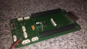
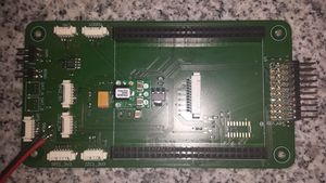
- 97 x 66 mm PCB
- 4 x status LED (USB red, USB green, power, USB OTG green, USB OTG red)
- LIS302DL MEMS 3 axis accelerometer on SPI1
Pinout
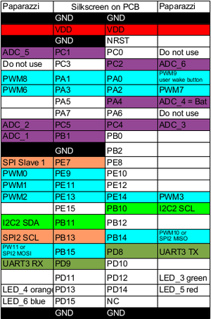
left pin bank in relation to paparazzi(not up to date!)
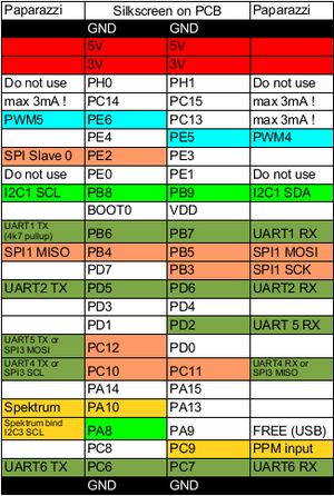
right pin bank in relation to paparazzi(not up to date!)
The Discovery has a male 100 pin (2x25pin on both sides, also accessible on both sides of the pcb) pinout.
LED
| Pin # |
Name |
Type |
Description |
Color
|
| PD13 |
LED_3 |
Out |
above LIS302DL |
Orange
|
| PD12 |
LED_4 |
Out |
left of LIS302DL |
Green
|
| PD14 |
LED_5 |
Out |
right of LIS302DL |
Red
|
| PD15 |
LED_6 |
Out |
below LIS302DL |
Blue
|
| PA9 |
LED_9 |
Out |
same as USB power (VBUS, needs to be enabled in header file |
Green
|
UART1
| Pin # |
Name |
Type |
Description
|
| PB6 |
UART1 TX |
Out |
UART1 Serial Output, 4k7 pullup for I2C
|
| PB7 |
UART1 RX |
In |
UART1 Serial Input
|
UART2
| Pin # |
Name |
Type |
Description
|
| PD5 |
UART2 TX |
Out |
UART2 Serial Output
|
| PD6 |
UART2 RX |
In |
UART2 Serial Input, also used for Spektrum input
|
UART3
| Pin # |
Name |
Type |
Description
|
| PD8 |
UART3 TX |
Out |
UART3 Serial Output
|
| PD9 |
UART3 RX |
In |
UART3 Serial Input
|
UART4 (Can NOT be used if SPI_3 is active!)
| Pin # |
Name |
Type |
Description
|
| PC10 |
UART4 TX |
Out |
UART4 Serial Output
|
| PC11 |
UART4 RX |
In |
UART4 Serial Input
|
UART5 (Can NOT be used if SPI_3 is active!)
| Pin # |
Name |
Type |
Description
|
| PC12 |
UART5 TX |
Out |
UART5 Serial Output
|
| PD2 |
UART5 RX |
In |
UART5 Serial Input
|
UART6
| Pin # |
Name |
Type |
Description
|
| PC6 |
UART6 TX |
Out |
UART6 Serial Output
|
| PC7 |
UART6 RX |
In |
UART6 Serial Input
|
SPI1 (for onboard LIS302DL)
| Pin # |
Name |
Type |
Description
|
| PA5 |
SPI1 SCK |
I/O |
SPI1 Serial clock
|
| PA6 |
SPI1 MISO |
I/O |
SPI1 Master In Slave Out
|
| PA7 |
SPI1 MOSI |
I/O |
SPI1 Master Out Slave In
|
| PE2 |
SPI SS0 |
I/O |
SPI1 Select Slave0
|
SPI1
| Pin # |
Name |
Type |
Description
|
| PB3 |
SPI1 SCK |
I/O |
SPI1 Serial clock
|
| PB4 |
SPI1 MISO |
I/O |
SPI1 Master In Slave Out
|
| PB5 |
SPI1 MOSI |
I/O |
SPI1 Master Out Slave In
|
| PE2 |
SPI SS0 |
I/O |
SPI1 Select Slave0
|
SPI2 (Can NOT be used if PWM10 & PWM11 is active!)
| Pin # |
Name |
Type |
Description
|
| PB13 |
SPI2 SCK |
I/O |
SPI2 Serial clock
|
| PB14 |
SPI2 MISO |
I/O |
SPI2 Master In Slave Out
|
| PB15 |
SPI2 MOSI |
I/O |
SPI2 Master Out Slave In
|
| PE7 |
SPI SS1 |
I/O |
SPI2 Select Slave1
|
SPI3 (Can NOT be used if UART4 & UART5 is active!)
| Pin # |
Name |
Type |
Description
|
| PC10 |
SPI3 SCK |
I/O |
SPI3 Serial clock
|
| PC11 |
SPI3 MISO |
I/O |
SPI3 Master In Slave Out
|
| PC12 |
SPI3 MOSI |
I/O |
SPI3 Master Out Slave In
|
| PE3 |
SPI SS2 |
I/O |
SPI3 Select Slave1
|
I2C1
| Pin # |
Name |
Type |
Description
|
| PB8 |
I2C1 SCL |
I/O |
I2C1 Serial Clock
|
| PB9 |
I2C1 SDA |
I/O |
I2C1 Serial Data
|
I2C2
| Pin # |
Name |
Type |
Description
|
| PB10 |
I2C2 SCL |
I/O |
I2C2 Serial Clock
|
| PB11 |
I2C2 SDA |
I/O |
I2C2 Serial Data
|
I2C3 (Can NOT be used if Spektrum bind / PPM input is active!)
| Pin # |
Name |
Type |
Description
|
| PA8 |
I2C3 SCL |
I/O |
I2C3 Serial Clock
|
| PC9 |
I2C3 SDA |
I/O |
I2C3 Serial Data
|
Note: is disabled in header file, PA8 is used as Spektrum bind pin, PC9 is used as PPM (not Spektrum) input
ADC
| Pin # |
Name |
Type |
Description
|
| PB1 |
AUX1 |
I/O |
ADC_1
|
| PC5 |
AUX2 |
I/O |
ADC_2
|
| PC4 |
AUX3 |
I/O |
ADC_3
|
| PA4 |
BAT |
I/O |
ADC_4, is used for BAT voltage
|
| PC1 |
AUX5 |
I/O |
ADC_5
|
| PC2 |
AUX6 |
I/O |
ADC_6
|
PWM
| Pin # |
Name |
Type |
Description
|
| PE9 |
PWM0 |
Out |
Servo 1
|
| PE11 |
PWM1 |
Out |
Servo 2
|
| PE13 |
PWM2 |
Out |
Servo 3
|
| PE14 |
PWM3 |
Out |
Servo 4
|
| PE5 |
PWM4 |
Out |
Servo 5
|
| PE6 |
PWM5 |
Out |
Servo 6
|
| PA3 |
PWM6 |
Out |
Servo 7
|
| PA2 |
PWM7 |
Out |
Servo 8
|
| PA1 |
PWM8 |
Out |
Servo 9
|
| PA0 |
PWM9 |
Out |
Servo 10
|
| PB14 |
PWM10 |
Out |
Servo 11, Can not be used if SPI2 is active
|
| PB15 |
PWM11 |
Out |
Servo 12, Can not be used if SPI2 is active
|
PPM
| Pin # |
Name |
Type |
Description
|
| PC9 |
PPM |
In |
PPM input (remember, you need 100 Ohm serial termination in order to use this)
|
Spektrum
| Pin # |
Name |
Type |
Description
|
| PA8 |
Bind |
Out |
Spektrum bind pin
|
| PA10 |
PPM |
IN |
Spektrum PPM in
|
Jumper
Jumper
| Pin # |
Name |
Type |
Description
|
| JP1 |
JP1 |
Switch |
MCU Current can be measured here
|
| CN3 |
CN3 |
Switch |
closed: STLinkV2 is connected to onboard MCU, open: is not connectec to onboard, only external header
|
Soolder Jumper
| Pin # |
Name |
Type |
Description
|
| SB17 |
SB17 |
Switch |
Bypass for JP1, close this for security ! (if JP1 gets loose)
|
Daughterboard
comming soon :) git repo
Components:
Diode: Standard types (like 1N4007) will work
Resistors: 2k2 and 22k, 0,1%
Caps: Low ESR type, 10-50µF
Firmware Flashing
FLASH_MODE=STLINK is set as default
STM32F4 Discovery can mainly be programmed in two different ways:
STLINK
- with onboard STLinkV2 over SWD
- required hardware: usb to mini USB cable
- required software: st_flash and st_util from Texane
- more information: STLink page
DFU-UTIL
- with the MCU native (embedded in rom) DFU USB bootloader over the micro USB AB connector
- required hardware: USB to micro and USB to mini usb cable
- required external software: dfu-util
- push MCU in DFU mode: connect mini(for power) and micro USB to PC, connect pin BOOT0 with 3V, press reset button(LED LD7 should light up now), disconnect BOOT0
- more information: DFU page


