Overview
Hardware Revision History
| Version # |
Release Date |
Release Notes
|
| v1.00 |
10/2016 |
Initial release of Chimera
|
Detailed Features
Pictures
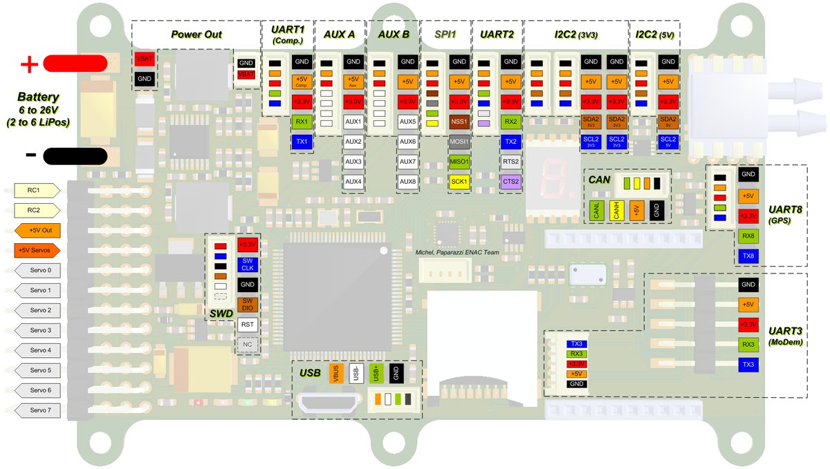
Pinout
Pins Name and Type are specified with respect to the Autopilot Board
General Pinout
Pinout Tables
UART1 (Companion)
| Pin # |
Name |
Type |
MCU Port |
Description
|
| 1 |
GND |
PWR |
- |
common ground
|
| 2 |
+5V Comp. |
PWR |
Controlled by
PC5 |
5V/3A specific for Companion board
(PC5 = LOW => ON (default, pulldown) / PC5 = High => OFF)
|
| 3 |
+3.3V |
PWR |
- |
3.3V Rail from autopilot
|
| 4 |
RX1 |
IN |
PB7 |
UART1 Serial Input (3.3V level, 5V tolerant)
|
| 5 |
TX1 |
OUT |
PB6 |
UART1 Serial Output (3.3V level)
|
UART2
| Pin # |
Name |
Type |
MCU Port |
Description
|
| 1 |
GND |
PWR |
- |
common ground
|
| 2 |
+5V |
PWR |
- |
5V Rail from autopilot
|
| 3 |
+3.3V |
PWR |
- |
3.3V Rail from autopilot
|
| 4 |
RX2 |
IN |
PD6 |
UART2 Serial Input (3.3V level, 5V tolerant)
|
| 5 |
TX2 |
OUT |
PD5 |
UART2 Serial Output (3.3V level)
|
| 6 |
RTS2 |
OUT |
PD4 |
UART2 Flow Control Request to Send (3.3V level)
|
| 7 |
CTS2 |
IN |
PD3 |
UART2 Flow Control Clear to Send (3.3V level, 5V tolerant)
|
UART3 (Modem)
| Pin # |
Name |
Type |
MCU Port |
Description
|
| 1 |
GND |
PWR |
- |
common ground
|
| 2 |
+5V |
PWR |
- |
5V Rail from autopilot
|
| 3 |
+3.3V |
PWR |
- |
3.3V Rail from autopilot
|
| 4 |
RX3 |
IN |
PD9 |
UART3 Serial Input (3.3V level, 5V tolerant) DO NOT USE if XBee module present on Chimera
|
| 5 |
TX3 |
OUT |
PD8 |
UART3 Serial Output (3.3V level) DO NOT USE if XBee module present on Chimera
|
UART8 (GPS Receiver)
| Pin # |
Name |
Type |
MCU Port |
Description
|
| 1 |
GND |
PWR |
- |
common ground
|
| 2 |
+5V |
PWR |
- |
5V Rail from autopilot
|
| 3 |
+3.3V |
PWR |
- |
3.3V Rail from autopilot
|
| 4 |
RX8 |
IN |
PE0 |
UART8 Serial Input (3.3V level, 5V tolerant)
|
| 5 |
TX8 |
OUT |
PE1 |
UART8 Serial Output (3.3V level)
|
I2C2 (3V3)
| Pin # |
Name |
Type |
MCU Port |
Description
|
| 1 |
GND |
PWR |
- |
common ground
|
| 2 |
+5V |
PWR |
- |
5V Rail from autopilot
|
| 3 |
+3.3V |
PWR |
- |
3.3V Rail from autopilot
|
| 4 |
SDA2 |
Open Drain
I/O |
PB11 |
I2C2 bus Serial DAta (3.3V level, 1.5k pull-up)
|
| 5 |
SCL2 |
Open Drain
I/O |
PB10 |
I2C12 bus Serial CLock (3.3V level, 1.5k pull-up)
|
Note: 2 x Molex Picoblade and 2 x 0.1" Header are all in parallel
I2C2 (5V)
| Pin # |
Name |
Type |
MCU Port |
Description
|
| 1 |
GND |
PWR |
- |
common ground
|
| 2 |
+5V |
PWR |
- |
5V Rail from autopilot
|
| 3 |
+3.3V |
PWR |
- |
3.3V Rail from autopilot
|
| 4 |
SDA2 |
Open Drain
I/O |
PB11 |
I2C2 bus Serial DAta (5V level, 3.3k pull-up)
|
| 5 |
SCL2 |
Open Drain
I/O |
PB10 |
I2C12 bus Serial CLock (5V level, 3.3k pull-up)
|
SPI1
| Pin # |
Name |
Type |
MCU Port |
Description
|
| 1 |
GND |
PWR |
- |
common ground
|
| 2 |
+5V |
PWR |
- |
5V Rail from autopilot
|
| 3 |
+3.3V |
PWR |
- |
3.3V Rail from autopilot
|
| 4 |
NSS1 |
OUT |
PA15 |
Slave Select. Selects the SPI slave
|
| 5 |
MOSI1 |
I/O |
PB5 |
SPI1 Master Out Slave In. Data output from master / data input to slave
|
| 6 |
MISO1 |
I/O |
PB4 |
SPI1 Master In Slave Out. Data input to master / data output from slave
|
| 7 |
SCK1 |
I/O |
PB3 |
SPI1 Serial clock. Clock output from master or input to slave
|
AUX A
| Pin # |
Name |
Type |
MCU Port |
Description
|
| 1 |
GND |
PWR |
- |
common ground
|
| 2 |
+5V Aux |
PWR |
Controlled by
PC4 |
5V from autopilot through Power Switch
(PC4 = LOW => OFF / PC4 = High => ON)
|
| 3 |
+3.3V |
PWR |
- |
3.3V Rail from autopilot
|
| 4 |
AUX0 |
I/O |
PA5 |
General Purpose I/O / ADC1+2 in5 / DAC2 / TIM2 ch1
|
| 5 |
AUX1 |
I/O |
PA3 |
General Purpose I/O / ADC1+2+3 in3 / TIM2 ch4 / TIM5 ch4 / TIM9 ch2
|
| 6 |
AUX2 |
I/O |
PA2 |
General Purpose I/O / ADC1+2+3 in2 / TIM2 ch3 / TIM5 ch3 / TIM9 ch1
|
| 7 |
AUX3 |
I/O |
PA0 |
General Purpose I/O / ADC1+2+3 in0 / TIM2 ch1 / TIM5 ch1
|
AUX B
| Pin # |
Name |
Type |
MCU Port |
Description
|
| 1 |
GND |
PWR |
- |
common ground
|
| 2 |
+5V |
PWR |
- |
5V Rail from autopilot
|
| 3 |
+3.3V |
PWR |
- |
3.3V Rail from autopilot
|
| 4 |
AUX4 |
I/O |
PC3 |
General Purpose I/O / ADC1+2+3 in13
|
| 5 |
AUX5 |
I/O |
PC2 |
General Purpose I/O / ADC1+2+3 in12
|
| 6 |
AUX6 |
I/O |
PC6 |
General Purpose I/O / TIM3 ch1 / TIM8 ch1 / UART6 TX
|
| 7 |
AUX7 |
I/O |
PC7 |
General Purpose I/O / TIM3 ch2 / TIM8 ch2 / UART6 RX
|
CAN
| Pin # |
Name |
Type |
MCU Port |
Description
|
| 1 |
GND |
PWR |
- |
common ground
|
| 2 |
+5V |
PWR |
- |
5V Rail from autopilot
|
| 3 |
CANH |
I/O |
- |
CAN bidirectional + line
|
| 4 |
CANL |
I/O |
- |
CAN bidirectional - line
|
Note: Embedded 120R terminator resistor.
USB
| Pin # |
Name |
Type |
MCU Port |
Description
|
| 1 |
GND |
PWR |
- |
common ground
|
| 2 |
USB+ |
I/O |
PA12 |
USB bidirectional D+ line
|
| 3 |
USB- |
I/O |
PA11 |
USB bidirectional D- line
|
| 4 |
VBUS |
IN |
PA9 |
Indicates the presence of USB bus power (5V level), DFU or USB storage Mode selection (BOOT0 MCU pin)
|
Note: MicroUSB, Molex Picoblade and 0.1" Header USB connectors are in parallel, only one can be connected at a time.
SWD (Serial Wire debug)
| Pin # |
Name |
Type |
MCU Port |
Description
|
| 1 |
+3.3V |
PWR |
- |
3.3V Rail from autopilot
|
| 2 |
SWCLK |
IN |
PA14 |
SWD Serial Clock
|
| 3 |
GND |
PWR |
- |
common ground
|
| 4 |
SWDIO |
I/O |
PA13 |
SWD Serial Data
|
| 5 |
RST |
IN |
NRST |
MCU Reset
|
| 6 |
NC |
- |
- |
Not connected, for STM ST-LINK/V2 connector compliance
|
Note: Pin to pin compatible with STM ST-LINK/V2 debug tool connector
Power Out
| Pin # |
Name |
Type |
Description
|
| 1 |
GND |
PWR |
common ground
use only to power peripheral modules, DO NOT use as power supply input for autopilot
|
| 2 |
VBAT |
PWR |
+ Rail from battery
use only to power peripheral modules, DO NOT use as power supply input for autopilot
|
Schematic
PCB
Gerber & Drill Files
Assembly
Components Layout
Bill Of Material
PCB and assembled boards suppliers
Check availability on Get Hardware page
Mechanical Dimensions
Programming
On-board Data Logging
Debugging
Debugging with STM Discovery ST-LINK/V2 embedded debug tool
Debugging with Black Magic Probe
Source Files
Source code
Where to Buy

