Previous Infrared Sensors
Jump to navigation
Jump to search
The printable version is no longer supported and may have rendering errors. Please update your browser bookmarks and please use the default browser print function instead.
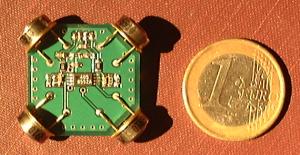
Dual Axis Board
Pinout
| Pin # | Name | Notes | Suggested Color |
|---|---|---|---|
| 1 | IR2 | IR Signal Output Axis 2 | Grey |
| 2 | GND | Ground | Black |
| 3 | VCC | +3.3v Power Supply | Red |
| 4 | IR1 | IR Signal Output Axis 1 | Braun |
Sensor Orientation
Align arrows FWD and AFT on fuselage, SM components up, Connector down. Either arrow can be forward. Follow Wiki airframe configuration file instructions.
Single Axis Board
Pinout
| Pin # | Name | Notes | Suggested Color |
|---|---|---|---|
| 1 | IR | IR Signal Output | Purple |
| 2 | VCC | +3.3v Power Supply | Red |
| 3 | GND | Ground | Black |
Sensor Orientation
 The sensor marked "TOP" goes up.
With the above "Sensor Orientation"s IR1_SIGN, IR2_SIGN, and TOP_SIGN values ended up "1" in the Airframe file. For more information look in ( ~/paparazzi3/sw/airborne/infrared.c ) file on your system.


