Difference between revisions of "Sensors/IR"
m |
|||
| (2 intermediate revisions by the same user not shown) | |||
| Line 1: | Line 1: | ||
__NOEDITSECTION__ | __NOEDITSECTION__ | ||
{| | {|class="MainPageBG" style="width:100%;border:0px solid #000;background-color:#fff;vertical-align:top;color:#000; text-align: left;" | ||
|-valign="top" | |-valign="top" | ||
| | | | ||
<h3 style="-moz-border-radius-topleft: 0em;-moz-border-radius-topright: 0.7em; | <h3 style="-moz-border-radius-topleft: 0em;-moz-border-radius-topright: 0.7em; | ||
background:# | background:#fff;margin:0px;padding:4px;border:1px solid #000;"> | ||
[[Image: | [[Image:Sensor.png|32px]] Infrared Sensors | ||
</h3> | </h3> | ||
<div style="padding:6px;"> | <div style="padding:6px;"> | ||
{{ | {{:Sensors/IR/Index}} | ||
</div> | </div> | ||
<!-- Start of right-column --> | <!-- Start of right-column --> | ||
| class="MainPageBG" style="width:70%;border: | | class="MainPageBG" style="width:70%;border:0px solid #000;background-color:#fff;vertical-align:top"| | ||
{|width="100%" cellpadding=" | {|width="100%" cellpadding="0" cellspacing="0" style="vertical-align:top;background-color:#fff" | ||
|-valign="top" | |-valign="top" | ||
| <h2 style="margin:0;background-color:# | | <h2 style="margin:0;background-color:#fff;font-size:120%;font-weight:bold;border:1px solid #000;text-align:left;color:#000;padding:4px;">[[Image:Sensor.png|32px]]Hardware support for previous and currently in use infrared boards.</h2> | ||
|- | |- | ||
| | | | ||
Latest revision as of 17:55, 19 January 2016
|
|
Infrared Theory
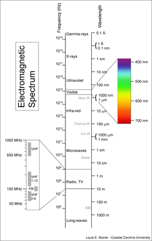
The infrared spectrum spans the gap between red light and microwave radiation and consists of a very large range of wavelengths from 0.75µm to 1000µm (compare to 0.38µm to 0.75µm for the entire range of visible light). With such a broad range, it is not surprising that the properties of IR radiation vary widely with wavelength and therefore are usually categorized as follows:
- near infrared (NIR, IR-A): 0.75–1.4 µm, this range is defined by the water absorption properties and is commonly used in fiber optic communication because of low attenuation losses in the SiO2 glass (silica) fiber.
- short wavelength IR (SWIR, IR-B): 1.4–3 µm, water absorption is substantial in this range.
- mid wavelength IR (MWIR, IR-C) also intermediate-IR (IIR): 3–8 µm
- long wavelength IR (LWIR, IR-C): 8–15 µm (The wavelength used by the Paparazzi IR sensors)
- far infrared (FIR): 15–1,000 µm (FIR lasers are used to detect explosives and chemical agents by infrared spectroscopy)
Near IR behaves much like red light, and can be focused in a glass lens or used to illuminate objects and is commonly used for dramatic effects in photography. Digital cameras are highly sensitive to NIR and typically include a filter to prevent this light from degrading the quality of the visible range.
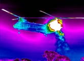
LWIR is more similar to microwave, and is a form of radiation emitted from within any material of any temperature above absolute zero. The emitted frequency is dependent on the temperature of the material and objects of common "earthly" temperatures typically emit radiation in the range of 8-12µm. The IR sensors used by Paparazzi are sensitive only to this range and therefore are not affected by objects of higher temperature, such as the sun. This range of IR passes easily through smoke and rain but can be blocked with a simple piece of clear tape.
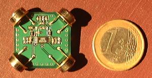
The IR thermopiles used for attitude detection use the thermoelectric effect to convert heat to voltage. They require no power and the voltage produced is extremely low ~ 40µV/K^4. To convert this low voltage into something that can be measured by the autopilot we first connect the sensors in geometrically opposed pairs and wire them together backwards - output-to-output, such that the system will produce 0V if the sensors are of equal temperature, and any difference between temperatures creates either a positive or negative voltage. Next we amplify this voltage by a factor of 500x and add a 1.65V DC offset. The result is that for normal earthly temperatures, the sensor pair will output a voltage of 0V - 3.3V at extreme temperature differences and 1.65V at equilibrium.
As the Earth emits substantially more IR radiation than the sky, we can always measure the difference between Earth and sky - even in cloudy/rainy weather, over snow covered land, or at night. The voltage produced by the sensor pair is proportional to two factors:
- The angle of the aircraft
- The local ground/sky temperature difference
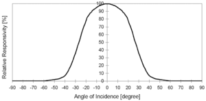
The sensors typically have a 100 degree field of view and produce a somewhat sinusoidal voltage response relative to their angle orientation. as seen in the plot to the right. By combining the data from 3 orthogonal pairs of sensors (X, Y, Z axes) we can compute the exact bank and pitch angles of the aircraft in any weather/terrain conditions with the following caveats:
- Thermopile response is not perfectly sinusoidal so some approximate correction factors must be manually tuned
- Thermopiles react slowly (~25ms time constant), producing a phase delay that can cause oscillation on agile airplanes if a gyro is not implemented
- Thermopiles must be dry. A water drop on the sensor will degrade its function. It is therefore not recommended to fly in precipitation or in heavy fog/clouds.
Related articles
Further infrared sensor information:
- "Horizon Sensing Attitude Stabilisation: A VMC Autopilot"
- "NASA Tech Note TN D-6616" and other NASA reports.
Infrared Stabilization Principle
The paparazzi autopilot uses infrared thermopiles for primary attitude sensing. The theory is that at zero bank or pitch angle, the difference in the heat between the two sensors should be zero, and at 90 degrees it should be maximum. From this relationship a linear regression is made and angles are calculated during flight.
Each pair of sensors measures one axis, a minimum of 2 pairs must be used to measure pitch and roll but best results are obtained thru the use of a 3rd pair on the vertical axis. Since the output signal from each sensor pair is proportional to both the attitude and the weather/terrain, systems with only x-y sensors require a ground calibration and may not provide accurate angle calculations as the aircraft travels over terrain with different IR radiation.
Hardware Architecture
Horizontal Board
Vertical Board
Thermopiles
The Thermopiles are:
- Manufacturer Part Number: MLX90247-ESF-DSA (Digi-Key)
- Description: IC SENS THERMOPILE W/THERM TO-39
- data sheet (Melexis site)


