Difference between revisions of "Rotorcraft Configuration"
(added octo mixing example) |
(added other octo configuration) |
||
| Line 202: | Line 202: | ||
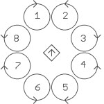
; Octo : [[Image:octo.jpg|border|200px]] | ; Octo (time cross): [[Image:octo.jpg|border|200px]] | ||
<source lang="xml"> | <source lang="xml"> | ||
<define name="ROLL_COEF" value="{ 106, -106, -256, -256, -106, 106, 256, 256 }"/> | <define name="ROLL_COEF" value="{ 106, -106, -256, -256, -106, 106, 256, 256 }"/> | ||
<define name="PITCH_COEF" value="{ 256, 256, 106, -106, -256, -256, -106, 106 }"/> | <define name="PITCH_COEF" value="{ 256, 256, 106, -106, -256, -256, -106, 106 }"/> | ||
<define name="YAW_COEF" value="{ -256, 256, -256, 256, -256, 256, -256, 256 }"/> | |||
<define name="THRUST_COEF" value="{ 256, 256, 256, 256, 256, 256, 256, 256 }"/> | |||
</source> | |||
; Octo (plus cross): rotor 1 on x-axis (image anyone?) | |||
<source lang="xml"> | |||
<define name="ROLL_COEF" value="{ 0, -181, -256, -181, 0, 181, 256, 181 }"/> | |||
<define name="PITCH_COEF" value="{ 256, 181, 0, -181, -256, -181, 0, 181 }"/> | |||
<define name="YAW_COEF" value="{ -256, 256, -256, 256, -256, 256, -256, 256 }"/> | <define name="YAW_COEF" value="{ -256, 256, -256, 256, -256, 256, -256, 256 }"/> | ||
<define name="THRUST_COEF" value="{ 256, 256, 256, 256, 256, 256, 256, 256 }"/> | <define name="THRUST_COEF" value="{ 256, 256, 256, 256, 256, 256, 256, 256 }"/> | ||
Revision as of 16:11, 1 April 2012
The airframe configuration file is located in conf/airframes and contains all the hardware and software settings for an aircraft. All gains, trims, and behavior settings are defined with standard XML elements. Optionally you can also add a raw Makefile section.
Firmware and Hardware definitions
This is one example of a pretty standard quadcopter firmware definition:
| File: conf/airframes/myplane.xml |
  <firmware name="rotorcraft">
    <target name="sim" board="pc">
      <subsystem name="fdm"   type="nps"/>
    </target>
    <target name="ap" board="booz_1.0"/>

    <define name="USE_ADAPT_HOVER"/>
    <define name="GUIDANCE_H_USE_REF"/>

    <subsystem name="radio_control" type="ppm"/>
    <subsystem name="telemetry"     type="transparent"/>
    <subsystem name="actuators"     type="mkk"/>
    <subsystem name="imu"           type="b2_v1.1"/>
    <subsystem name="gps"           type="ublox"/>
    <subsystem name="ahrs"          type="int_cmpl_quat"/>
    <subsystem name="stabilization" type="euler"/>
  </firmware>
|
Select your Board
The airframe file must include the description of the controller board and it's low-level settings. This is done in the firmware section by specifying the board attribute for the target "ap" (autopilot).
Select the appropriate board: "twog_1.0", "tiny_2.11", "tiny_2.1", "tiny_1.1", "tiny_0.99", "booz_1.0", "lisa_l_1.0", "lisa_l_1.1", "pc"
| File: conf/airframes/myplane.xml |
  <firmware name="rotorcraft">
    <target name="sim" 			board="pc"/>
    <target name="ap" 			board="booz_1.0"/>
     ...
  </firmware>
|
Actuators
You have to specify which ESCs you have by adding the appropriate actuators subsystem.
| File: conf/airframes/myplane.xml |
  <firmware name="rotorcraft">
    <target name="ap" board="booz_1.0"/>
     ...
    <subsystem name="actuators" type="mkk"/>
  </firmware>
|
INS
The optional INS (Integrated Navigation System) subsystem contains estimations filter to e.g. fuse GPS and IMU data for better position and speed estimates.
| File: conf/airframes/myplane.xml |
  <firmware name="rotorcraft">
    <target name="ap" board="booz_1.0"/>
     ...
    <subsystem name="ins" type="hff"/>
  </firmware>
|
You can also compensate for GPS lag in hff (horizontal filter float) if it is known (in seconds):
| File: conf/airframes/myplane.xml |
  <firmware name="rotorcraft">
    <target name="ap" board="booz_1.0"/>
     ...
    <subsystem name="ins" type="hff">
      <define name="GPS_LAG=0.2"/>
    </subsystem>
  </firmware>
|
Autopilot modes
For rotorcrafts we have a lot of different modes that can be mapped to your 3-position switch (Manual, Auto1, Auto2). The horizontal and vertical mode can be set differently as the following possible modes indicate:
- AP_MODE_FAILSAFE
This is a failsafe mode that gets triggered if:
- RC signal is lost (and you are not in KILL or NAV mode)
- GPS and RC is lost in NAV mode
The autopilot will level the rotorcraft out (setpoints to zero pitch and roll angles) and descend at 0.5m/s downwards.
- AP_MODE_KILL
Motors are simply switched off.
- AP_MODE_RATE_DIRECT
This is basically the "most" manual mode you can get. You control not the attitude (roll and pitch angles) but the rotation rate. You also set the throttle directly with your RC.
- AP_MODE_ATTITUDE_DIRECT
You control the attitude (roll, pitch and yaw angles), but the throttle directly proportional to your stick position.
- AP_MODE_RATE_RC_CLIMB
You control the rotation rate and the vertical speed according to your throttle stick position. If you have your throttle stick in the middle position, the altitude is keept, down goes down at a speed proportional to your stick position (same for up). In this mode it makes sense to mount the spring for your throttle stick so it recenter itself.
- AP_MODE_ATTITUDE_RC_CLIMB
You control the attitude (roll, pitch and yaw angles) and the vertical speed according to your throttle stick position. If you have your throttle stick in the middle position, the altitude is keept, down goes down at a speed proportional to your stick position (same for up). In this mode it makes sense to mount the spring for your throttle stick so it recenter itself.
- AP_MODE_ATTITUDE_CLIMB
You control the attitude (roll, pitch and yaw angles) and the vertical speed. The vertical speed is set via fms (e.g. joystick).
- AP_MODE_RATE_Z_HOLD
You control the rotation rate and it holds the altitude you were at when entering this mode. Your throttle stick position still limits the max throttle authority, so you should push your throttle stick up after entering this mode so the vertical controller has some "room" to stabilize the altitude. Should something weird happen you can limit the max thrust by taking throttle back.
- AP_MODE_ATTITUDE_Z_HOLD
You control the attitude (roll, pitch and yaw angles) and it holds the altitude you were at when entering this mode. Your throttle stick position still limits the max throttle authority, so you should push your throttle stick up after entering this mode so the vertical controller has some "room" to stabilize the altitude. Should something weird happen you can limit the max thrust by taking throttle back.
- AP_MODE_HOVER_DIRECT
The rotorcraft hovers at the horizontal position you were at when entering this mode (position control). You still set the throttle directly with your RC.
- AP_MODE_HOVER_CLIMB
The rotorcraft hovers at the position you were at when entering this mode (position control). The vertical speed is set via fms (e.g. joystick).
- AP_MODE_HOVER_Z_HOLD
The rotorcraft hovers at the 3D position you were at when entering this mode (position and altitude control). Your throttle stick position still limits the max throttle authority, so you should push your throttle stick up after entering this mode so the vertical controller has some "room" to stabilize the altitude. Should something weird happen you can limit the max thrust by taking throttle back.
- AP_MODE_NAV
Full navigation mode. The rotorcraft follows your flightplan.
XML Parameters
Mode
In the mode section you can set the autopilot modes associated with your 3-way mode switch on your RC.
  <section name="MODE" prefix="MODE_">
    <define name="MANUAL" value="AP_MODE_ATTITUDE_DIRECT" />
    <define name="AUTO1" value="AP_MODE_ATTITUDE_Z_HOLD" />
    <define name="AUTO2" value="AP_MODE_HOVER_Z_HOLD" />
  </section>
Commands
The commands lists the abstract commands you need to control the aircraft. For most multicopter you just need:
  <commands>
    <axis name="PITCH" failsafe_value="0"/>
    <axis name="ROLL" failsafe_value="0"/>
    <axis name="YAW" failsafe_value="0 />
    <axis name="THRUST" failsafe_value="0"/>
  </commands>
Each command is also associated with a failsafe value which will be used if no controller is active, for example during initialization of the autopilot board.
Supervision
This section describes the "mixing" used for your particular multirotor configuration. This section is needed for "mkk" (mikrokopter), "pwm_supervision" and "asctecV2" controllers, as "asctecV1" do their mixing themselves.
  <section name="SUPERVISION" prefix="SUPERVISION_">
    <define name="STOP_MOTOR" value="0"/> <!-- this defaults to zero, set to a different value if needed, e.g. for pwm controllers -->
    <define name="MIN_MOTOR" value="3"/>
    <define name="MAX_MOTOR" value="200"/>
    <define name="TRIM_A" value="0"/>
    <define name="TRIM_E" value="0"/>
    <define name="TRIM_R" value="0"/>
    <define name="NB_MOTOR" value="4"/>
    <define name="SCALE" value="256"/>
    <define name="ROLL_COEF"   value="{  0  ,    0,  256, -256 }"/>
    <define name="PITCH_COEF"  value="{  256, -256,    0,    0 }"/>
    <define name="YAW_COEF"    value="{ -256, -256,  256,  256 }"/>
    <define name="THRUST_COEF" value="{  256,  256,  256,  256 }"/>
  </section>
- STOP_MOTOR
- actuator specific command value to stop the motors
- MIN_MOTOR
- actuator specific command value for idling motors
- MAX_MOTOR
- actuator specific command value for maximum power
- TRIM_A
- trim added to roll command
- TRIM_E
- trim added to pitch command
- TRIM_R
- trim added to yaw command
- x_COEF
- roll/pitch/yaw/thrust coefficients, see RotorcraftMixing for details or the examples below
If your rotors are spinning opposite to the direction shown in the picture, just reverse signs in the YAW_COEF line.
- Plus Cross
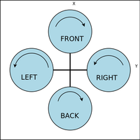

Assuming that the order of motors, described in the "servos" section is FRONT, BACK, LEFT, RIGHT.
    <define name="ROLL_COEF"   value="{    0,    0,  256, -256 }"/>
    <define name="PITCH_COEF"  value="{  256, -256,    0,    0 }"/>
    <define name="YAW_COEF"    value="{ -256, -256,  256,  256 }"/>
    <define name="THRUST_COEF" value="{  256,  256,  256,  256 }"/>
- Time Cross
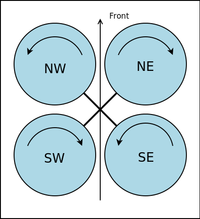

Assuming that the order of motors, described in the "servos" section is NE, SE, SW, NW.
    <define name="ROLL_COEF"   value="{ -256, -256,  256,  256 }"/>
    <define name="PITCH_COEF"  value="{  256, -256, -256,  256 }"/>
    <define name="YAW_COEF"    value="{ -256,  256, -256,  256 }"/>
    <define name="THRUST_COEF" value="{  256,  256,  256,  256 }"/>
- Octo (time cross)

    <define name="ROLL_COEF"   value="{  106, -106, -256, -256, -106,  106,  256,  256 }"/>
    <define name="PITCH_COEF"  value="{  256,  256,  106, -106, -256, -256, -106,  106 }"/>
    <define name="YAW_COEF"    value="{ -256,  256, -256,  256, -256,  256, -256,  256 }"/>
    <define name="THRUST_COEF" value="{  256,  256,  256,  256,  256,  256,  256,  256 }"/>
- Octo (plus cross)
- rotor 1 on x-axis (image anyone?)
    <define name="ROLL_COEF"   value="{    0, -181, -256, -181,    0,  181,  256,  181 }"/>
    <define name="PITCH_COEF"  value="{  256,  181,    0, -181, -256, -181,    0,  181 }"/>
    <define name="YAW_COEF"    value="{ -256,  256, -256,  256, -256,  256, -256,  256 }"/>
    <define name="THRUST_COEF" value="{  256,  256,  256,  256,  256,  256,  256,  256 }"/>
If you want to compute mixing for a special configuration, please see the RotorcraftMixing page.
Simulation
Values from this section can be used to tweak the SITL simulation. The NPS (New Paparazzi Sim) currently uses JSBSim as for the flight dynamic modeling, but other FDMs are possible.
<section name="SIMULATOR" prefix="NPS_">
<define name="ACTUATOR_NAMES" value="{"front_motor", "back_motor", "right_motor", "left_motor"}" />
<define name="INITIAL_CONDITITONS" value=""reset00"" />
<define name="SENSORS_PARAMS" value=""nps_sensors_params_booz2_a1.h"" />
</section>
Control Loops
The control loops for rotorcraft can be found in Control Loops.