Difference between revisions of "RC Receivers and Radios"
| Line 215: | Line 215: | ||
[[Image:Corona_Synthesized_Receiver_72Mhz_top_atmel.jpg]] | [[Image:Corona_Synthesized_Receiver_72Mhz_top_atmel.jpg]] | ||
<br> | <br style="clear:both"> | ||
==433MHz UHF Systems== | ==433MHz UHF Systems== | ||
| Line 222: | Line 222: | ||
===Scherrer UHF=== | ===Scherrer UHF=== | ||
[[Image:ScherrerUHF.jpg|thumb|left|Scherrer UHF Rx]] | |||
The [http://www.webx.dk/rc/uhf-link3/uhf-link3.htm Scherrer UHF] is a high quality diversity radio control system. It has a PPM output and can be connected directely to Paparazzi. A ppm encoder board is not required. It has an RSSI output. | The [http://www.webx.dk/rc/uhf-link3/uhf-link3.htm Scherrer UHF] is a high quality diversity radio control system. It has a PPM output and can be connected directely to Paparazzi. A ppm encoder board is not required. It has an RSSI output. | ||
<br style="clear:both"> | |||
===ImmersionRC EzUHF=== | ===ImmersionRC EzUHF=== | ||
[[Image:EzUHFTx.jpg|thumb|left|ImmersionRC Tx]] | |||
The [http://www.immersionrc.com/products.htm ImmersionRC EzUHF] is a high quality diversity radio control system. It does not have a PPM output. A ppm encoder board is required. It connects directely to EzOSD and the TrackR2 which enables easy RSSI monitoring and head tracking for FPV. | The [http://www.immersionrc.com/products.htm ImmersionRC EzUHF] is a high quality diversity radio control system. It does not have a PPM output. A ppm encoder board is required. It connects directely to EzOSD and the TrackR2 which enables easy RSSI monitoring and head tracking for FPV. | ||
<br style="clear:both"> | |||
Revision as of 14:07, 19 August 2010
2.4GHz Systems
To use a 2.4 GHz system a few requirements are necessary
- Must use ppm encoder board. (See Get Hardware page for suppliers) (Except for the Futaba FASST 7 channel receiver R617FS that has a 5 (not 7) channels combined pulse)
- Needs a three position switch
- Ability to set failsafe to any or at least 1 channel (pprz-mode) as desired
- At least one extra channel beyond those needed to control the servos and motor. (throttle-roll-pitch-mode)
Radios
Futaba FASST 7-channel receiver

- Pin 8 (upper right corner in picture) of the small IC on the right contains 5 PPM pulses and can go directly to paparazzi. Pulse 6 and 7 go directly to the servos.
- Best is to remove the resistors of one of the channels and connect a small wire to pin 8 to get the combined 5 pulses on the robust 1/10th inch header.
- Do not forget to use channel 3 (only failsafe channel) as mode switch with fail safe "throttle off" as mode 2.
Spektrum DX-7

- 7 Channels
- 20-Model memory
- Airplane and Heli software
- Switch assignment
- P-mixes
- Includes 4 powerful DS821 digital servos with high-tech resin gears
- 3-axis dual rate & expo
- 3-position flap (Airplane)
- 5-point throttle curve (Heli)
- 3 flight modes plus hold (Heli)
- Gyro programming (Heli)
- CCPM, 2-servo 90°, 3-servo 90°, & 3-servo 120°
- Price $320-$350
Switch Assignment
To assign the three position switch to any other channel but channel 7 follow these steps:
- Set up aux2(refers to aux2 on rx not the switch on the tx. aka ch7) with its input selected as 3 pos switch.
- Set up this mix - Gear to Gear (Up=-100, Down=-100, Offset =0). This inhibits the gear switch.
- Set up another mix - Aux2 to Gear (Up=100, Down=100, Offset = 0).
Notes:
- Gear on a DX-7 Air is Channel 5 and AUX2 is CH7. Once again i am referring to the inputs which are labeled on the RX not what the switches are named on the TX. If your using a DX-7 heli please substitute the names for what the rx channels are named into this guide
- DX7 Heli the 3-pos switch is named "flight mode"
- DX7 Air the 3-pos switch is named "flaps"
Failsafe Setup
To set up the mode channel (3 pos switch) to default to auto2 if connection is lost between rx and tx follow these steps:
- Put 3 position Switch into AUTO2 Position
- Put in bind plug
- Power up
- REMOVE the bind plug
- Power up Tx while pushing bind button
- Wait until light becomes steady and not blinking (it may become steady right off but will then start blinking again so let it go at least 5 seconds)
PCM Systems
- Must use ppm encoder board. (See Get Hardware page for suppliers)
- Needs a three position switch
- Ability to set failsafe to any channel as desired
- At least one extra channel beyond those needed to control the servos and motor.
PPM Based Systems
Configuration
The Radio_Control page describes how to set up the radio.xml config file.
Requirements
To use a 72/35/40/41 MHz **(uses ppm) system a few requirements are necessary
- Need a Transmitter with a three position switch
- At least one extra channel beyond those needed to control the servos and motor.
- A modified receiver which outputs the ppm signal.
Adding a 3 position switch
Futaba T6EXAP
For this particular transmitter, the Potentiometer on channel 6 can be replaced with a 3 position switch. Channel 5 appears not to be connected to an ADC converter; therefore it will not support a 3 position switch.
- Disconnect the potentiometer being careful not to shorten the wires
- Solder the switch and resistors onto the wires using the wiring diagram as a reference. (Any two equal value resistors should work). I used 10k resistors.


Suitable 3 position switches:
RS Components: 344-710
Mouser: 633-M202402-RO
R/C Receiver Interface
All versions of the Paparazzi autopilot include a connector to interface with a standard R/C receiver for manual or semi-autonomous control during the testing and tuning phases. Two interface options exist:
- Tap into the PPM signal running between the RF section and the servo driver of your receiver and route it to the Paparazzi. Let the Paparazzi generate individual servo signals and connect all servos directly to the autopilot. This method requires only 3 wires to the receiver (power and PPM), is compatible with all Paparazzi autopilots, and provides 8 manual R/C channels and the potential for more autonomous channels regardless of the capability of the R/C receiver.
- Cut the PPM trace and route it thru the autopilot and back to the receiver, using the servo driver IC on your R/C receiver to drive the servos. This option requires 4 wires (Ground, PPM-in, PPM-out, Reset) and your receiver must have a supported servo driver IC. This allows you to use the large servo connectors on your R/C receiver and does not require any modification to your servos or ESC but does require you to cut a trace on your R/C receiver and limits the number of servos to the capacity of your receiver. Compatible with Classix and Tiny 1.1.
- Note that on the Classix the PPM_in pin is FOO2...


Common demux chips
Typical used chips are the cmos 4015 and 4017.
The 4015 uses either pin 1 or pin 9 for the clock and the input is on 7 and 15. The 4017 has just one shift register and has its clock input on pin 14 and the enable on pint 13.
In most receivers you are after the clock; though some may be pulsed; in which case you need the enable. Note that the 4017 enable has inverted logic (low to be enabled) whereas the input on the 4015 can be either (typically high). If the enable pin is held low (4017) or if the input pin (4015) is held high always;e.g. connected to the ground or the Vcc - then it is fair to assume that the PPM signal is most propably on the clock input.
Recommended 35/40Mhz R/C Receivers
Note that there is information on modifying other receiver models at mikrokopter.de. It's in German however the pictures contain most of the information or use google translate. Shielded wire is recommended for receiver and autopilot connection, as unshielded one may cause noise in receiver.
Futaba FP-R116FB 6 Channel FM 35MHz receiver

- Orange wire is connected to PPM signal
- Red wire is connected to VCC
- Brown wire is connected to GND
Futaba R136F 6 Channel FM receiver

- 41 MHz
- White wire is connected to PPM signal
Futaba R168DF 8 Channel dual FM receiver

- 35 MHz
- PPM wire is connected to 862 receiver pin on the board. VCC and GND is on the 8/B original position.
ACT Micro-6 FM receiver

- Available in 35 or 40 MHz versions
- White wire is connected to PPM signal
- Datasheet (German)
ACT DSL-4top mikrokopter.de version

- Special version for mikrokopter.de - Only available in their shop!
- Outputs PPM directly on the channel 1 connector!
- No soldering necessary
- ACT Lifetime warranty
- Sells for ~45 euro
Futaba R115F 5 Channel FM receiver

- Available in 35 and 40 MHz versions
- White wire is connected to PPM signal
JETI REX 5 plus (no MPD) receiver

- Popular Czech made micro r/c receiver, available in 35 or 40 MHz versions
- ´folded´ PCB design with parts inside, mostly inaccessable
- Small grey wire is connected to via with PPM signal
- Unusual connector used for testing, soldering recommended
- shielded wire recommended, this one taken from PC parts recycling (former soundcard to m/b connector cable)
- Datasheet (English)

Receiver RX-7-SYNTH IPD receiver Multiplex-rc.de

- Available in 35 and 40 MHz versions
- A compact, high-quality 7-channel single-conversion FM / PPM IPD receiver
- Easy modification through connectors, see pictures
Protech 5FM 35 mHz Receiver
The low cost Protech '5FM' receiver makes use of an SMD version of the standard 74AHC164[1] 8 bit shift register; you are after PIN 1 of this chip. The circuit board has a testpad for just this pin at the top side of the circuit board.
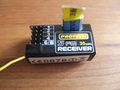
Figure 1.
Protech 5FM 35 mHZ Receiver, mark 2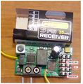
Figure 2.
PPM tap location for the Protech 5FM receiver, near the 74AHC164 shift register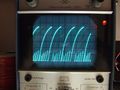
Figure 3.
Protech 5FM PPM signal - not very clean/digital


Two physical versions exist; the older one [2] and a newer one pictured (fig 1). It has been distributed by protech with various ready-to-fly planes; such as the Skyraider[3].
The solder/testpad you are after the one right next the 74x164 chip its pin 1. In this image it has a jellow wire soldered to it (the yellow wire at the top left is the normal antenna connector (fig 2). Note however that the signal is not very clean (1v/div) - which may cause issues - as shown in the above image (fig 3).
This is further compunded by the relatively noisy electrical engines; which are not brushless. A ferrite coil does not seem to help enough - Papparazi and GPS loose sync often through Xbee. Replacing the engine by a brushless outrunnen resolve the issue completely.
Profi Penta 35 MHz


Recommended 72Mhz R/C Receivers
Castle Creations Berg 4L

- Expect fantastic performance from these $40 USD parts but be warned that they are known to have unreliable crystal sockets and brittle antenna wire. The Berg 7 channel receiver should work equally well and is known to have a better crystal socket - note that either receiver will provide 8 channels in manual R/C mode when used with Paparazzi. Note: the rugged Berg 4 cannot be modified, only the Berg 4L and Berg 7.
To Modify a Berg4L, follow these instructions:
- Remove the shrink wrap. Use a good knife and be careful to not damage any of the components on the receiver. I would recommend that you cut on the sides (edge of the PCB) to be sure to avoid damaging the shielding
- Desolder the headers. We will not use them with tiny AP as the servos are connected directly to the AP. This is pretty easy to do when you have a hot air rework station. If you don't have one, your best bet is to cut the header off and remove the left over pins one by one with a regular iron. There is a piece of shielding material that is connected to one of the ground pins of the header. You need to remove it carefully from the header without damaging it and re-solder it to the gnd pad.
- You need to solder 3 wires to the receiver. Gnd, +5V and PPM. To locate the PPM signal, first locate the PIC micro controller close to the location of the headers. The PPM signal is on the corner pin closest to the corner of the receiver. Soldering a 28guage wire directly to the PIN isn't very difficult. For the power connection, use the pads that were used for the header. The outside pin is Gnd, the second pin is +5V. What I did is solder the wires on the pad going straight down, then I looped the 3 wires 360 degrees and glued them to the PCB with hot glue. This provides good strain relief.
- While you have the PCB in your hands, take the opportunity to remove the crystal connector and solder your crystal directly to the PCB for added reliability.
- I also used some hot glue to add more strain relief to the antenna
- Use some large shrink wrap to cover the entire receiver again
Hitec Electron 6 72MHz Reciever
This was written for MNAV from crossbow but is still usable with PPRZ.

Corona Synthesized Dual-Conv Receiver 8Ch
This receiver is available in 27,35,36,40,72 mhz and a Synthesized receiver, meaning you do not need to change frequency crystals.
How to modify for combined signal
- Cut the 8th channel PWM output pin near the PCB.
- Connected a pin from the Atmel (see picture) to the 8th channel PWM signal. (optionally, weaving the wire through some holes on the board.) Make sure you have a fine tip on your soldering iron and a magnifying glass strapped to your head!
- Glue the wire down (CA works)
- Be sure to glue the pin that you cut in place (previously, being soldered to the board was holding the pin in place)
It is maybe possible to reprogram the atmel with your own firmware. If you succeed in this plz add relevant info here.
That pin provides a 1V to 2V signal, it works with the PPRZ, although its a bit gittery (the slew rate is not real good).


433MHz UHF Systems
Note that in most countries an amateur radio license is required to use 433MHz UHF.
Scherrer UHF

The Scherrer UHF is a high quality diversity radio control system. It has a PPM output and can be connected directely to Paparazzi. A ppm encoder board is not required. It has an RSSI output.
ImmersionRC EzUHF

The ImmersionRC EzUHF is a high quality diversity radio control system. It does not have a PPM output. A ppm encoder board is required. It connects directely to EzOSD and the TrackR2 which enables easy RSSI monitoring and head tracking for FPV.