Difference between revisions of "DevGuide/DesignOverview"
Corybarton (talk | contribs) |
|||
| Line 204: | Line 204: | ||
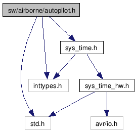
This is a sample of a Doxygen Graph: | This is a sample of a Doxygen Graph: | ||
[[Image:Autopilot_8h_incl.png|Include dependency graph for autopilot.h]] | [[Image:Autopilot_8h_incl.png|Include dependency graph for autopilot.h]] | ||
[[Category:Software]] [[Category:Hardware]] [[Category:Developer_Documentation]] | |||
Revision as of 17:41, 9 March 2011
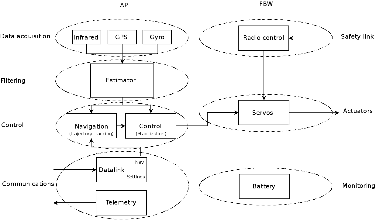
Airborne Functional Diagram
Design Goals
-Static approach
-Modularity
-Hardware absraction
-Runtime efficiency
Static Approach
 -only "things that needs to be changed during flight are changeable
 -maximise compilation time resolutions
 advantages
   Error checking
   Efficiency
   Safety/Robustness
Modularity
 -Separation of concerns
 -Maintenability
 -Interface
 -C provide no dedicated mechanism for modularity
 -Main issues with modularity are configuration and dependancies
Hardware abstraction
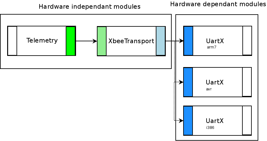
-Segregate hardware dependant modules
Runtime Efficiency
It's very unlikely that we will change the serial port on which we connected our modem inflight.
 bad :
switch(UART) {
 case UART0 : UARTO_write(...); break;
 case UART1 : UART1_write(...); break;
}
 good :
#define UartWrite(x) UART ## _write(x)
UartWrite(...);
Design Solutions
* Heavy pre-processor usage
* C code generation
* Heavy Makefile usage
* Conventions to define our own module layer
pre-processor
header selection
conf/airframes/funjet1.xml
<makefile>
ap.CFLAGS += -DACTUATORS=\"servos_4017_hw.h\"
</makefile>
generated var/FJ1/Makefile.ac
ap.CFLAGS += -DACTUATORS=\"servos_4017_hw.h\"
sw/airborne/actuators.h
#include ACTUATORS
expanded by pre-processor to
#include "servos_4017_hw.h"
macros
conf/airframes/funjet1.xml
ap.CFLAGS += -DXBEE_UART=Uart1
sw/airborne/xbee.h
 #define __XBeeLink(dev, _x) dev##_x
 #define _XBeeLink(dev, _x) __XBeeLink(dev, _x)
 #define XBeeLink(_x) _XBeeLink(XBEE_UART, _x)
 #define XBeeBuffer() XBeeLink(ChAvailable())
expanded by pre-processor to
Uart1ChAvailable()
C code generation
For problems too complex to solve with the pre processor, we use custom compilers to generate code from a description in xml
example 1 : command laws, aka mixers
conf/airframes/funjet1.xml
<command_laws>
 <let var="aileron" value="@ROLL * AILEVON_AILERON_RATE"/>
 <let var="elevator" value="@PITCH * AILEVON_ELEVATOR_RATE"/>
 <set servo="AILEVON_LEFT" value="$elevator + $aileron"/>
 <set servo="AILEVON_RIGHT" value="$elevator - $aileron"/>
</command_laws>
generated var/FJ1/airframe.h
#define SetActuatorsFromCommands(values) { \
  uint16_t servo_value;\
  float command_value;\
  int16_t _var_aileron = values[COMMAND_ROLL] * AILEVON_AILERON_RATE;\
  int16_t _var_elevator = values[COMMAND_PITCH] * AILEVON_ELEVATOR_RATE;\
[....]
  command_value = _var_elevator + _var_aileron;\
  command_value *= command_value>0 ? SERVO_AILEVON_LEFT_TRAVEL_UP :   SERVO_AILEVON_LEFT_TRAVEL_DOWN;\
  servo_value = SERVO_AILEVON_LEFT_NEUTRAL + (int16_t)(command_value);\
  actuators[SERVO_AILEVON_LEFT] = ChopServo(servo_value, SERVO_AILEVON_LEFT_MIN, SERVO_AILEVON_LEFT_MAX);\
  Actuator(SERVO_AILEVON_LEFT) = SERVOS_TICS_OF_USEC(actuators[SERVO_AILEVON_LEFT]);\
example 2 : flight plan
conf/flight plans/example.xml
  <block name="For loop (circles wp 1)">
     <for from="0" to="3" var="i">
       <circle radius="DEFAULT_CIRCLE_RADIUS+ $i*10" wp="1" until="NavCircleCount() > 1"/>
     </for>
     <deroute block="Standby"/>
   </block>
generated var/flight plan.h
 Block(29) // For loop (circles wp 1)
   switch(nav_stage) {
     static int8_t _var_i;
     static int8_t _var_i_to;
     Stage(0)
       _var_i = 0 - 1;
       _var_i_to = 3;
     Label(for_11)
     Stage(1)
       if (++_var_i > _var_i_to) Goto(endfor_12) else NextStageAndBreak();
       Stage(2)
         NavVerticalAutoThrottleMode(RadOfDeg(0.000000));
         NavVerticalAltitudeMode(WaypointAlt(3), 0.);
         NavCircleWaypoint(3, (DEFAULT_CIRCLE_RADIUS+(_var_i*10)));
         if ((NavCircleCount()>1)) NextStageAndBreak();
         break;
       Stage(3)
         Goto(for_11)
       Label(endfor_12)
     Stage(5)
       NextBlock();
       break;
   }
Makefile
Connecting and configuring modules
 ap.CFLAGS += -DDOWNLINK -DDOWNLINK_TRANSPORT=XBeeTransport -DXBEE_UART=Uart1
 ap.srcs += downlink.c xbee.c
 ap.CFLAGS += -DUSE_UART1 -DUART1_BAUD=B9600
 ap.srcs += \$(SRC_ARCH)/uart_hw.c
Modules configuration
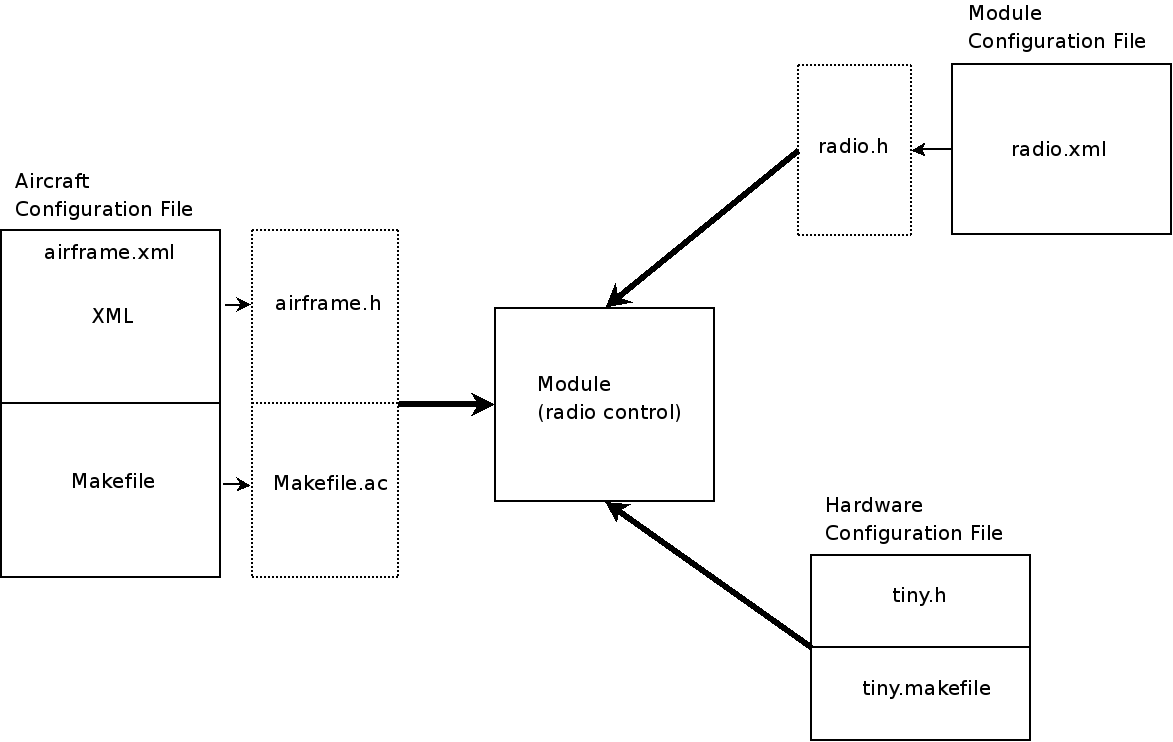
3 sources of configuration:
 * airframe configuration file ( airframe.xml ) which "compiled" to C files and Makefile
 * specific per module configuration file ( eg radio.xml, flightplan.xml) compiled to C code to allow factorization between airframes.
 * specific per board configuration file ( eg tiny.h ) to describe modules configuration imposed by board routing
Conventions
Generating Doxygen Code Documentation
A way to look at the includes and dependencies is to use the graphs generated with doxygen. After installing Paparazzi, install Doxygen:
sudo apt-get install doxygen graphviz
run the generation tool from the paparazzi3/ directory:
make doxygen
Now Doxygen will have generated html documentation(open this with any web browser) in your paparazzi3/dox/html folder.
To look at a list of all of the files used by the airborne software:
paparazzi3/dox/html/files.html
The main_ap.c will also interest you.
paparazzi3/dox/html/main__ap_8c.html


