Difference between revisions of "DevGuide/DesignOverview"
| (10 intermediate revisions by 7 users not shown) | |||
| Line 1: | Line 1: | ||
== Airborne Functional Diagram == | == Airborne Functional Diagram == | ||
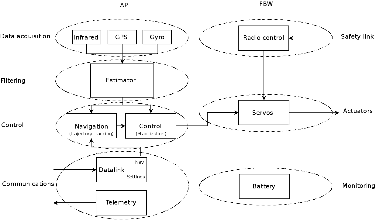
[[Image:Airborne_software_functional.png]] | |||
== Generating Doxygen Code Documentation == | |||
see [[Doxygen]] | |||
== Previous designs == | |||
The documentation below this point reflects older version of paparazzi below v5.x | |||
=== Airborne Functional Diagram === | |||
[[Image:functional_diagram.png]] | [[Image:functional_diagram.png]] | ||
== Design Goals == | === Design Goals === | ||
-Static approach | -Static approach | ||
-Modularity | -Modularity | ||
-Hardware | -Hardware abstraction | ||
-Runtime efficiency | -Runtime efficiency | ||
=== Static Approach === | ==== Static Approach ==== | ||
-only "things that needs to be changed during flight are changeable | -only "things that needs to be changed during flight are changeable | ||
-maximise compilation time resolutions | -maximise compilation time resolutions | ||
| Line 18: | Line 29: | ||
Safety/Robustness | Safety/Robustness | ||
=== Modularity === | ==== Modularity ==== | ||
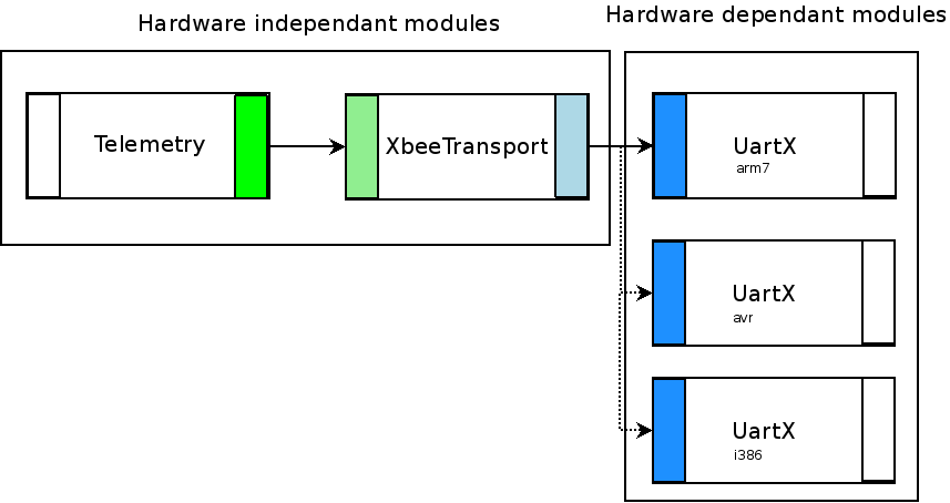
[[Image:modularity.png]] | [[Image:modularity.png]] | ||
| Line 30: | Line 41: | ||
[[Image:dependancies_example.png]] | [[Image:dependancies_example.png]] | ||
=== Hardware abstraction === | ==== Hardware abstraction ==== | ||
-Segregate hardware dependant modules | -Segregate hardware dependant modules | ||
| Line 37: | Line 48: | ||
=== Runtime Efficiency === | ==== Runtime Efficiency ==== | ||
We have to take care that our code runs efficient on the autopilot board microprocessor. It is for example very unlikely that we will physically change the serial port on which we connected our telemetry modem during a flight. | |||
'''bad''' coding practice | |||
switch(UART) { | switch(UART) { | ||
case UART0 : UARTO_write(...); break; | case UART0 : UARTO_write(...); break; | ||
| Line 46: | Line 59: | ||
} | } | ||
'''good''' coding practice | |||
#define UartWrite(x) UART ## _write(x) | #define UartWrite(x) UART ## _write(x) | ||
UartWrite(...); | UartWrite(...); | ||
=== Design Solutions === | |||
== Design Solutions == | |||
* Heavy pre-processor usage | * Heavy pre-processor usage | ||
| Line 59: | Line 72: | ||
=== pre-processor === | ==== pre-processor ==== | ||
==== header selection ==== | ===== header selection ===== | ||
conf/airframes/funjet1.xml | conf/airframes/funjet1.xml | ||
| Line 72: | Line 85: | ||
ap.CFLAGS += -DACTUATORS=\"servos_4017_hw.h\" | ap.CFLAGS += -DACTUATORS=\"servos_4017_hw.h\" | ||
sw/airborne/actuators.h | |||
#include ACTUATORS | #include ACTUATORS | ||
| Line 80: | Line 94: | ||
==== macros ==== | ===== macros ===== | ||
conf/airframes/funjet1.xml | |||
ap.CFLAGS += -DXBEE_UART=Uart1 | ap.CFLAGS += -DXBEE_UART=Uart1 | ||
sw/airborne/xbee.h | |||
#define __XBeeLink(dev, _x) dev##_x | #define __XBeeLink(dev, _x) dev##_x | ||
#define _XBeeLink(dev, _x) __XBeeLink(dev, _x) | #define _XBeeLink(dev, _x) __XBeeLink(dev, _x) | ||
| Line 97: | Line 111: | ||
=== C code generation === | ==== C code generation ==== | ||
For problems too complex to solve | For problems too complex to solve with the pre processor, we use custom compilers to generate code from a description in xml | ||
==== example 1 : command laws, aka mixers ==== | ===== example 1 : command laws, aka mixers ===== | ||
conf/airframes/funjet1.xml | conf/airframes/funjet1.xml | ||
<command_laws> | <command_laws> | ||
<let var="aileron" value="@ROLL * AILEVON_AILERON_RATE"/> | <let var="aileron" value="@ROLL * AILEVON_AILERON_RATE"/> | ||
<let var="elevator" value="@PITCH * AILEVON_ELEVATOR_RATE"/> | <let var="elevator" value="@PITCH * AILEVON_ELEVATOR_RATE"/> | ||
<set servo="AILEVON_LEFT" value="$elevator + $aileron"/> | <set servo="AILEVON_LEFT" value="$elevator + $aileron"/> | ||
<set servo="AILEVON_RIGHT" value="$elevator - $aileron"/> | <set servo="AILEVON_RIGHT" value="$elevator - $aileron"/> | ||
</command_laws> | </command_laws> | ||
generated var/FJ1/airframe.h | generated var/FJ1/airframe.h | ||
#define SetActuatorsFromCommands(values) { \ | #define SetActuatorsFromCommands(values) { \ | ||
uint16_t servo_value;\ | |||
float command_value;\ | |||
int16_t _var_aileron = values[COMMAND_ROLL] * AILEVON_AILERON_RATE;\ | |||
int16_t _var_elevator = values[COMMAND_PITCH] * AILEVON_ELEVATOR_RATE;\ | |||
[....] | [....] | ||
command_value = _var_elevator + _var_aileron;\ | |||
command_value *= command_value>0 ? SERVO_AILEVON_LEFT_TRAVEL_UP : SERVO_AILEVON_LEFT_TRAVEL_DOWN;\ | |||
servo_value = SERVO_AILEVON_LEFT_NEUTRAL + (int16_t)(command_value);\ | |||
actuators[SERVO_AILEVON_LEFT] = ChopServo(servo_value, SERVO_AILEVON_LEFT_MIN, SERVO_AILEVON_LEFT_MAX);\ | |||
Actuator(SERVO_AILEVON_LEFT) = SERVOS_TICS_OF_USEC(actuators[SERVO_AILEVON_LEFT]);\ | |||
==== example 2 : flight plan ==== | ===== example 2 : flight plan ===== | ||
conf/flight plans/example.xml | conf/flight plans/example.xml | ||
<block name="For loop (circles wp 1)"> | |||
<for from="0" to="3" var="i"> | |||
<circle radius="DEFAULT_CIRCLE_RADIUS+ $i*10" wp="1" until="NavCircleCount() > 1"/> | |||
</for> | |||
<deroute block="Standby"/> | |||
</block> | |||
generated var/flight plan.h | generated var/flight plan.h | ||
Block(29) // For loop (circles wp 1) | |||
switch(nav_stage) { | |||
static int8_t _var_i; | |||
static int8_t _var_i_to; | |||
Stage(0) | |||
_var_i = 0 - 1; | |||
_var_i_to = 3; | |||
Label(for_11) | |||
Stage(1) | |||
if (++_var_i > _var_i_to) Goto(endfor_12) else NextStageAndBreak(); | |||
Stage(2) | |||
NavVerticalAutoThrottleMode(RadOfDeg(0.000000)); | |||
NavVerticalAltitudeMode(WaypointAlt(3), 0.); | |||
NavCircleWaypoint(3, (DEFAULT_CIRCLE_RADIUS+(_var_i*10))); | |||
if ((NavCircleCount()>1)) NextStageAndBreak(); | |||
break; | |||
Stage(3) | |||
Goto(for_11) | |||
Label(endfor_12) | |||
Stage(5) | |||
NextBlock(); | |||
break; | |||
} | |||
=== Makefile === | ==== Makefile ==== | ||
==== Connecting and configuring modules ==== | ===== Connecting and configuring modules ===== | ||
ap.CFLAGS += -DDOWNLINK -DDOWNLINK_TRANSPORT=XBeeTransport -DXBEE_UART=Uart1 | ap.CFLAGS += -DDOWNLINK -DDOWNLINK_TRANSPORT=XBeeTransport -DXBEE_UART=Uart1 | ||
| Line 160: | Line 181: | ||
ap.CFLAGS += -DUSE_UART1 -DUART1_BAUD=B9600 | ap.CFLAGS += -DUSE_UART1 -DUART1_BAUD=B9600 | ||
ap.srcs += \$(SRC_ARCH)/uart_hw.c | ap.srcs += \$(SRC_ARCH)/uart_hw.c | ||
===== Modules configuration ===== | |||
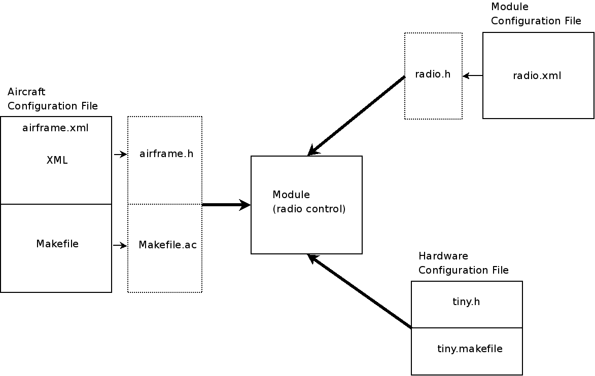
3 sources of configuration: | |||
* airframe configuration file ( airframe.xml ) which "compiled" to C files and Makefile | |||
* specific per module configuration file ( eg radio.xml, flightplan.xml) compiled to C code to allow factorization between airframes. | |||
* specific per board configuration file ( eg tiny.h ) to describe modules configuration imposed by board routing | |||
[[Image:modules_configuration.png]] | |||
==== Conventions ==== | |||
[[Category:Software]] [[Category:Hardware]] [[Category:Developer_Documentation]] | |||
Latest revision as of 15:21, 18 April 2015
Airborne Functional Diagram
Generating Doxygen Code Documentation
see Doxygen
Previous designs
The documentation below this point reflects older version of paparazzi below v5.x
Airborne Functional Diagram
Design Goals
-Static approach
-Modularity
-Hardware abstraction
-Runtime efficiency
Static Approach
 -only "things that needs to be changed during flight are changeable
 -maximise compilation time resolutions
 advantages
   Error checking
   Efficiency
   Safety/Robustness
Modularity
 -Separation of concerns
 -Maintenability
 -Interface
 -C provide no dedicated mechanism for modularity
 -Main issues with modularity are configuration and dependancies
Hardware abstraction
-Segregate hardware dependant modules
Runtime Efficiency
We have to take care that our code runs efficient on the autopilot board microprocessor. It is for example very unlikely that we will physically change the serial port on which we connected our telemetry modem during a flight.
bad coding practice
switch(UART) {
 case UART0 : UARTO_write(...); break;
 case UART1 : UART1_write(...); break;
}
good coding practice
#define UartWrite(x) UART ## _write(x)
UartWrite(...);
Design Solutions
* Heavy pre-processor usage
* C code generation
* Heavy Makefile usage
* Conventions to define our own module layer
pre-processor
header selection
conf/airframes/funjet1.xml
<makefile>
ap.CFLAGS += -DACTUATORS=\"servos_4017_hw.h\"
</makefile>
generated var/FJ1/Makefile.ac
ap.CFLAGS += -DACTUATORS=\"servos_4017_hw.h\"
sw/airborne/actuators.h
#include ACTUATORS
expanded by pre-processor to
#include "servos_4017_hw.h"
macros
conf/airframes/funjet1.xml
ap.CFLAGS += -DXBEE_UART=Uart1
sw/airborne/xbee.h
 #define __XBeeLink(dev, _x) dev##_x
 #define _XBeeLink(dev, _x) __XBeeLink(dev, _x)
 #define XBeeLink(_x) _XBeeLink(XBEE_UART, _x)
 #define XBeeBuffer() XBeeLink(ChAvailable())
expanded by pre-processor to
Uart1ChAvailable()
C code generation
For problems too complex to solve with the pre processor, we use custom compilers to generate code from a description in xml
example 1 : command laws, aka mixers
conf/airframes/funjet1.xml
<command_laws>
 <let var="aileron" value="@ROLL * AILEVON_AILERON_RATE"/>
 <let var="elevator" value="@PITCH * AILEVON_ELEVATOR_RATE"/>
 <set servo="AILEVON_LEFT" value="$elevator + $aileron"/>
 <set servo="AILEVON_RIGHT" value="$elevator - $aileron"/>
</command_laws>
generated var/FJ1/airframe.h
#define SetActuatorsFromCommands(values) { \
  uint16_t servo_value;\
  float command_value;\
  int16_t _var_aileron = values[COMMAND_ROLL] * AILEVON_AILERON_RATE;\
  int16_t _var_elevator = values[COMMAND_PITCH] * AILEVON_ELEVATOR_RATE;\
[....]
  command_value = _var_elevator + _var_aileron;\
  command_value *= command_value>0 ? SERVO_AILEVON_LEFT_TRAVEL_UP :   SERVO_AILEVON_LEFT_TRAVEL_DOWN;\
  servo_value = SERVO_AILEVON_LEFT_NEUTRAL + (int16_t)(command_value);\
  actuators[SERVO_AILEVON_LEFT] = ChopServo(servo_value, SERVO_AILEVON_LEFT_MIN, SERVO_AILEVON_LEFT_MAX);\
  Actuator(SERVO_AILEVON_LEFT) = SERVOS_TICS_OF_USEC(actuators[SERVO_AILEVON_LEFT]);\
example 2 : flight plan
conf/flight plans/example.xml
  <block name="For loop (circles wp 1)">
     <for from="0" to="3" var="i">
       <circle radius="DEFAULT_CIRCLE_RADIUS+ $i*10" wp="1" until="NavCircleCount() > 1"/>
     </for>
     <deroute block="Standby"/>
   </block>
generated var/flight plan.h
 Block(29) // For loop (circles wp 1)
   switch(nav_stage) {
     static int8_t _var_i;
     static int8_t _var_i_to;
     Stage(0)
       _var_i = 0 - 1;
       _var_i_to = 3;
     Label(for_11)
     Stage(1)
       if (++_var_i > _var_i_to) Goto(endfor_12) else NextStageAndBreak();
     Stage(2)
       NavVerticalAutoThrottleMode(RadOfDeg(0.000000));
       NavVerticalAltitudeMode(WaypointAlt(3), 0.);
       NavCircleWaypoint(3, (DEFAULT_CIRCLE_RADIUS+(_var_i*10)));
       if ((NavCircleCount()>1)) NextStageAndBreak();
       break;
     Stage(3)
       Goto(for_11)
     Label(endfor_12)
     Stage(5)
       NextBlock();
       break;
   }
Makefile
Connecting and configuring modules
 ap.CFLAGS += -DDOWNLINK -DDOWNLINK_TRANSPORT=XBeeTransport -DXBEE_UART=Uart1
 ap.srcs += downlink.c xbee.c
 ap.CFLAGS += -DUSE_UART1 -DUART1_BAUD=B9600
 ap.srcs += \$(SRC_ARCH)/uart_hw.c
Modules configuration
3 sources of configuration:
 * airframe configuration file ( airframe.xml ) which "compiled" to C files and Makefile
 * specific per module configuration file ( eg radio.xml, flightplan.xml) compiled to C code to allow factorization between airframes.
 * specific per board configuration file ( eg tiny.h ) to describe modules configuration imposed by board routing


