Apogee/v1.00


Overview
- STMicroelectronics STM32F405RGT6 Cortex M4 168MHz processor featuring a Floating point unit (FPU), up to 192k of RAM and 1024k of FLASH.
- 9(6) DOF integrated IMU MPU-9150(6050) based
- 1 x Barometer/altimeter MPL3115A2 (I2C, MPU slave capability)
- 1 x MicroSD card slot, 4 bit SDIO interface (high speed data logging)
- 1 x USB : DFU mode (download) or USB storage (direct access to MicroSD card)
- 6 x Servo PWM outputs
- 1 x R/C receiver PPM frame input
- 1 x R/C receiver serial input with inverter (Futaba S.BUS, Spektrum, etc.)
- 3 x UART
- 2 x I2C bus
- 1 x SPI bus
- RTC with backup capacitor
- SWD(ARM download/debug interface)
- 4 x Auxiliary I/O (General Purpose and/or ADC and/or servo PWM)
- 5v / 1.5A switching power supply (input voltage range 5.5V min → 17.0v max)
- 3.3v / 1A linear regulator
- 1 x 5v / 500mA power switch
- 4 x status LEDs
- 10.4 grams (0.37 oz)
- 53 x 25mm (2.1" x 0.98"), shares the same external dimensions and mounting points as UmarimLite
- 4 layers PCB design
Hardware Revision History
| Version # | Release Date | Release Notes |
|---|---|---|
| v1.00 | 07/2013 | Initial release of Apogee |
Detailed Features
SDIO (MicroSD card)
- software support available with v5.2 and above
- hi-cap power designed to give enough time to cleanly save buffer and close file(s) when power outage detected
- USB-storage mode when plugging an USB cable after startup
6 or 9 DOF IMU
Apogee v1.00 PCB offer two Invensense IMU chip options:
- MPU-6050 : 6 DOF, 3 axis Accelerometer + 3 axis Gyroscope
- MPU-9150 : 9 DOF, 3 axis Accelerometer + 3 axis Gyroscope + 3 axis Magnetometer
USB Modes
- usb plugged before autopilot is powered : enter DFU mode to be flashed
- usb plugged after autopilot is powered : stop ap task, enter usb storage mode to made sdcard content easily avalaible, after the host has mounted;copied;dismounted storage;unplugged usb, ap restart
SWD: Serial Wire Debug
permits flash and source level debugging via swd part of cheap discovery card, or via more capable, fastest, more expensive probe like black magic probe
R/C Serial
In addition to the classic PPM input, that mostly require receiver modification, one pin of the R/C connector is routed to the MCU UART2 receive input through a controlled inverter.
This new feature allow direct connection (3 pin) of several brand off-the-shelf receivers without hardware modification or external encoder board.
- RX2_POL(PB13) = 0 => R/C serial (Rx2) is non-inverted : allow use standard polarity serial receivers (Spektrum, FlyElectric...)
- RX2_POL(PB13) = 1 => R/C serial (Rx2) is inverted : allow use of S.BUS protocol compatible receivers (Futaba, FrSky,...)
(see R/C Receivers and Radios page for serial compatible receiver)
Real Time Clock
supercap powered rtc, permit to associate correct time and date on sdcard log files, when ap is unpowered between flights
Power Switch
5V power output pin on AUX connector ("5Vaux",#2) can be switched ON and OFF on demand using APSW (MCU GPIO output PB12).
- APSW = 0 => 5V Aux OFF
- APSW = 1 => 5V Aux ON (default)
The internal switch TPS2051B is designed to withstand 500mA continuous current and is short-circuit and thermally protected.
(see TPS2051B datasheet for recommended operation conditions)
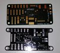
Pictures
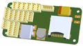
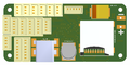
Apogee v1.00 3D bottom view
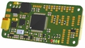
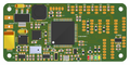
Apogee v1.00 3D top view
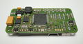
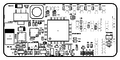
Apogee v1.00 bottom view
Apogee v1.00 top view
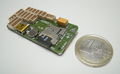
Apogee v1.00 and Umarim-Lite
footprint comparison


Pinout
Pins Name and Type are specified with respect to the Autopilot Board

| Pin # | Name | Type | Description |
|---|---|---|---|
| 1 | GND | PWR | common ground |
| 2 | +5V | PWR | 5V Rail from autopilot |
| 3 | SRVx | OUT | Servo signal (PWM) |
| Pin # | Name | Type | Description |
|---|---|---|---|
| 1 | GND | PWR | common ground |
| 2 | +5v | PWR | 5V Rail from autopilot |
| 3 | PPM in | IN | PPM Stream from R/C Receiver (5V tolerant) |
| 4 | RX2 | IN | UART2 Serial Input (5V Tolerant) through controlled inverter |
| Pin # | Name | Type | Description |
|---|---|---|---|
| 1 | GND | PWR | common ground |
| 2 | +5V | PWR | 5V Rail from autopilot |
| 3 | +3.3V | PWR | 3.3V Rail from autopilot |
| 4 | RX1/4/6 | IN | UART1/4/6 Serial Input (3.3V level, UART1 and UART6 are 5V tolerant, UART4 IS *NOT* 5V tolerant) |
| 5 | TX1/4/6 | OUT | UART1/4/6 Serial Output (3.3V level) |
| Pin # | Name | Type | Description |
|---|---|---|---|
| 1 | GND | PWR | common ground |
| 2 | +5V | PWR | 5V Rail from autopilot |
| 3 | +3.3V | PWR | 3.3V Rail from autopilot |
| 4 | SDA1/2 | Open Drain I/O (1.5k pull-up) |
I2C1/2 bus Serial DAta |
| 5 | SCL1/2 | Open Drain I/O (1.5k pull-up) |
I2C1/2 bus Serial CLock |
| Pin # | Name | Type | Description |
|---|---|---|---|
| 1 | GND | PWR | common ground |
| 2 | USB+ | I/O | USB bidirectional D+ line |
| 3 | USB- | I/O | USB bidirectional D- line |
| 4 | VBUS | IN | Indicates the presence of USB bus power (5V level), DFU or USB storage Mode selection |
Note: MiniUSB and Molex USB connectors are in parallel, only one can be connected at a time.
| Pin # | Name | Type | Description |
|---|---|---|---|
| 1 | GND | PWR | common ground |
| 2 | +5V | PWR | 5V Rail from autopilot |
| 3 | +3.3V | PWR | 3.3V Rail from autopilot |
| 4 | CS1 | OUT | Slave Select. Selects the SPI slave (PB9) |
| 5 | MOSI1 | I/O | SPI1 Master Out Slave In. Data output from master / data input to slave |
| 6 | MISO1 | I/O | SPI1 Master In Slave Out. Data input to master / data output from slave |
| 7 | SCK1 | I/O | SPI1 Serial clock. Clock output from master or input to slave |
| Pin # | Name | Type | Port | Description |
|---|---|---|---|---|
| 1 | GND | PWR | common ground | |
| 2 | +5Vaux | PWR | 5V from autopilot through Power Switch | |
| 3 | +3.3V | PWR | 3.3V Rail from autopilot | |
| 4 | AUX1 | I/O | PB1 | General Purpose I/O #1 or ADC_1 Input or PWM6 |
| 5 | AUX2 | I/O | PC5 | General Purpose I/O #2 or ADC_2 Input |
| 6 | AUX3 | I/O | PC4 | General Purpose I/O #3 or ADC_3 Input |
| 7 | AUX4 | I/O | PB15 | General Purpose I/O #4 (also spektrum bind pin) |
| Pin # | Name | Type | Description |
|---|---|---|---|
| 1 | GND | PWR | common ground |
| 2 | +3.3V | PWR | 3.3V Rail from autopilot |
| 3 | RST | IN | MCU Reset |
| 4 | SWCLK | IN | Serial Wire Clock |
| 5 | SWDIO | I/O | Serial Wire Data Input/Output |
Schematic

PCB
Gerber & Drill Files
PCB design Eurocircuits 6-C class compliant:
Download Apogee v1.00 gerber & drill files (zip)
RS274X, units = Inches, format = 2:5
- Apogee_v100_Silkscreen_TOP.GBR (Top Component Print Layer)
- Apogee_v100_Soldermask_Top.GBR (Top Solder Mask)
- Apogee_v100_Paste_Mask_Top.GBR (Top Paste Mask, stencil)
- Apogee_v100_Signal_Top.GBR (Top Copper Layer)
- Apogee_v100_Internal_Plane_1.GBR (Internal Copper Layer GND)
- Apogee_v100_Internal_Plane_2.GBR (Internal Copper Layer +3.3V)
- Apogee_v100_Signal_Bottom.GBR (Bottom Copper Layer)
- Apogee_v100_Paste_Mask_Bottom.GBR (Bottom Paste, stencil)
- Apogee_v100_Soldermask_Bottom.GBR (Bottom Solder Mask)
- Apogee_v100_Outline.GBR (Board Outline)
- Apogee_v100_Drill.GBR (NC XY coordinates & Drill tools sizes)
Assembly
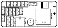
Components Layout
Apogee v1.00 bottom components Layout
Apogee v1.00 top components Layout
Apogee v1.00 bottom components detail
Apogee v1.00 top components detail


Bill Of Material
Download Apogee v1.00 Bill of Material (zipped .xls file)
PCB and assembled boards suppliers
Check availability on Get Hardware page
Mechanical Dimensions


Programming
Apogee autopilot can reprogrammed in two different ways:
- using the MCU native (embedded in rom) DFU USB bootloader over the on-board USB header (so pre-loading an "external" bootloader is useless)
- required hardware : usb cable with usb-mini connector
- required software : dfu_util tool (present in ubuntu repository)
- using the SWD (Serial Wire Debug) connector
- required hardware : usb cable with usb-mini connector, molex to 2.54mm pitch pin cable, swd part of a cheap stm32 evaluation board (any discovery board, start @ 8$)
- required software : st_flash and st_util, have to be compiled from source (https://github.com/texane/stlink)
On-board Data Logging
It is possible to write data on the embedded SD card from the main autopilot program. In order to cope with a real-time constraints of the autopilot, a light RTOS called ChibiOS is used to split the logging task from the rest of the system. Two modules are necessary to enable the logging system: the driver of the SD card system that also handle the file system (using FATFS) and a dynamic memory allocation system called TLSF. In order to enable this features for your apogee board, you need to select the correct board type and add the required modules to the firmware section of your airframe file (logging is currently only available for fixedwing firmware):
<firmware name="firmware">
 ...
 <target name="ap" board="apogee_1.0_chibios">
   ...
 </target>
 ...
 <module name="tlsf"/>
 <module name="logger" type="sd_chibios"/>
</firmware>
This will active the automatic opening of a new log file (30 seconds) after each startup of the autopilot. Then you can freely write ASCII or binary data into this file (see a simple example logging for meteorological data logging). The file is automatically closed upon battery disconnection, no need to press any button to stop the logging.
To recover the data on the SD card, just power up the board without the USB plugged (otherwise it will enter in DFU boot mode), then plus the USB cable to the board and to your computer. This will stop the main autopilot program and will mount the SD card as a regular mass storage with a FAT file system. The log files are placed in a PPRZ folder. Unplugging the USB will reset the autopilot.
In addition to this, you can also load a flight recorder module (it also needs the pprzlog module for supporting the specific paparazzi binary log format).
<firmware>
 ...
 <module name="pprzlog"/>
 <module name="flight_recorder"/>
 ...
</firmware>
with the appropriate telemetry file (conf/telemetry/fixedwing_flight_recorder.xml). This will automatically open a second file where telemetry messages described in the FlightRecorder section of the telemetry file will be logged in binary format. The files are store in a separated FR folder on the SD card. The decoding procedure is the same than OpenLog and is using the sd2log tool:
~/paparazzi/sw/logalizer/sd2log [log_file] [optinal_output_dir]
This will produce 3 files: a .log and a .data files similar to the normal ground station log and .tlm file that is a simple copy of the binary file (but rename with the same base name than the two others).
Debugging
Debugging with STM Discovery ST-LINK/V2 embedded debug tool

Debugging with CricketProbe

Debugging with Black Magic Probe

Source Files
Apogee v1.00 hardware design (zipped Protel99SE SP6 database file)
Source code
Available in latest git master branch
Where to Buy
You can purchase Apogee V1.00 from one of the following stores: