CricketProbe/v1.00
The CricketProbe is a debugging tool for ARM Cortex Microprocessors.
It is a Black Sphere Technologies Black Magic Probe PCB re-design, with some improvements made to the connectors, and is fully software-compatible.

Hardware Revision History
| Version # | Release Date | Release Notes |
|---|---|---|
| v1.00 (current) | 04/2014 | Initial release |
| v0.00 | 02/2014 | Prototype |
Detailed Features
Fully compatible with the Black Magic Probe, the features are identical:
(following is a copy of Black Magic Probe's webpage)
- Aimed at ARM Cortex based microcontrollers.
- Allows direct connection to the targeted processors JTAG interface. Alternatively, you may use the ARM Serial Wire Debug protocol as well.
- Full debugging functionality is provided. This includes: watchpoints, flash memory breakpoints, memory and register examination, flash memory programming, etc.
- Multiple targets on a single JTAG scan chain is supported.
- Interface to the host computer is a standard USB CDC ACM device (a virtual serial port), which does not require special drivers on Linux.
- Implements the GDB extended remote debugging protocol for seamless integration with the GNU debugger and other GNU development tools.
- Implements USB DFU class for easy firmware upgrades (as updates become available).
- Windows, Linux and Mac environments supported.
This board allows you to:
- Load your application into the target processor Flash memory or RAM.
- Single step through your program.
- Run your program in real-time with halt on demand.
- Examine and modify CPU registers and memory.
- Obtain a call stack backtrace.
- Set up to 6 hardware assisted breakpoints.
- Set up to 4 hardware assisted read, write or access watchpoints.
- Set unlimited software breakpoints when executing your application from RAM.
Pictures
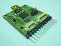
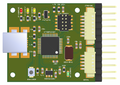
Side view
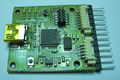
Top view
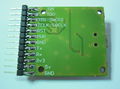
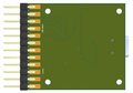
Bottom view
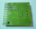
Bottom view w/o header


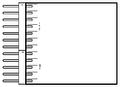
Pinout
Pins Name and Type are specified with respect to the CricketProbe Board

Schematic

PCB
Gerber & Drill Files
2 Layers PCB design Eurocircuits 6-C class compliant:
Download CricketProbe v1.00 gerber & drill files (zip)
RS274X, units = Inches, format = 2:5
- CricketProbe_v100_Silkscreen_Top.GBR (Top Print Layer)
- CricketProbe_v100_Soldermask_Top.GBR (Top Solder Mask)
- CricketProbe_v100_Paste_Mask_Top.GBR (Top Paste Mask, stencil)
- CricketProbe_v100_Signal_Top.GBR (Top Copper Layer)
- CricketProbe_v100_Signal_Bottom.GBR (Bottom Copper Layer)
- CricketProbe_v100_Soldermask_Bottom.GBR (Bottom Solder Mask)
- CricketProbe_v100_Silkscreen_Bottom.GBR (Bottom Print Layer)
- CricketProbe_v100_Outline.GBR (Board Outline)
- CricketProbe_v100_Drill.GBR (NC XY coordinates & Drill tools sizes)
Assembly
Components Layout
CricketProbe v1.00 top components Layout
CricketProbe v1.00 bottom components Layout
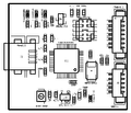
CricketProbe v1.00 top components detail
CricketProbe v1.00 bottom components detail


Bill Of Material
Download CricketProbe v1.00 Bill of Material (zipped .xls file)
PCB and assembled boards suppliers
Check availability on Get Hardware page
OSH Park PCB
If you like to order from the OSH Park PCB pooling service, there is a project you can order: CricketProbe v1.00 OSH Park
Mechanical Dimensions

Programming
"Factory" (Bootloader) Programming

Getting, compiling flashing firmware
Since the criquet probe is an accurate copy of black magic probe, the black magic probe documentation applies.
Here is an abstract of the software installation.
You will need the same cross compiler as used by paparazzi, so, if you already use paparazzi, this point is already done. This procedure assume that your are using a linux box. For a macosx gear, it will be different, feel free to complete the wiki if you know how to do the job from a mac.
Get and compile source from GitHub:
git clone https://github.com/gsmcmullin/blackmagic.git
cd blackmagic
git submodule init
git submodule update
make
Flash the bootloader via a STLink (all STM32 Discovery boards provide one onboard) with st-flash onto the criquet MCU:
- remove the two programming jumper on the discovery card (refer to the discovery card stm32 documentation)
- wire discovery SWD connector to criquet probe (cf upper shematic) (disco-swdio => criquetprobe-rx ; disco-swclk => criquetprobe-tx ; ground connected)
- plug discovery on an usb port on your computer
- load the bootloader : st-flash write ./src/blackmagic_dfu.bin 0x08000000
- unplug the discovery (and don't forget to put back the jumpers if you want to use it again as a discovery board)
Still need one step to have a useful device, see on next chapter how to program black magic gdb client firmware.
Firmware Upgrade
This requires an functional bootloader (see previous chapter).
- cd the rootdir of previously downloaded git repository
- maintain the small black button of the criquet probe while connecting it to computer via usb.
- the red led should be flashing, indicating that the criquet wait for firmware upload
- sudo ./scripts/stm32_mem.py src/blackmagic.bin
- unplug and replug usb
should be done