Sensors
Infrared Sensors

The paparazzi autopilot uses infrared thermopiles for primary attitude sensing. The theory is that at zero bank or pitch angle, the difference in the heat between the two sensors should be zero, and at 90 degrees it should be maximum. From this relationship a linear regression is made and angles are calculated during flight. Each pair of sensors measures one axis, a minimum of 2 pairs must be used to measure pitch and roll but best results are obtained thru the use of a 3rd pair on the vertical axis. Since the output signal from each sensor pair is proportional to both the attitude and the weather/terrain, systems with only x-y sensors require a ground calibration and may not provide accurate angle calculations as the aircraft travels over terrain with different IR radiation.
Architecture

Dual Axis Board Pinout

Single Axis Board Pinout

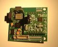
Below is a product designed by FMA Direct and is a replacement for their Flight Stabilization system. With a simple resistor swap, this module is suitable for use in the Paparazzi UAV.
FMA Direct CoPilot Sensor Head


Stock FMA Components
The stock FMA resistors R2/R3 and R5/R6 (0.8 Mohm/510 ohm) set the op amp gain to approximately 1600. Since this unit is designed to run on 5V and we are running it on 3.3V, it is advised to change R3 and R6 from 510 ohm to 1K ohm for an approximate gain of approximately 800. Without the change, it is theoretically possible to overdrive the Op Amp in extreme hot regions/seasons.
Another resistor swap option for this board is to replace R2 and R5 with 560 Kohm resistors, generating an output gain of approximately 1100; a gain which is practically identical to that of the Paparazzi board.
| R1 | 200 ohm |
| R2 | 0.8 Mohm |
| R3 | 510 ohm |
| R4 | 200 ohm |
| R5 | 0.8 Mohm |
| R6 | 510 ohm |
| R7 | 600 ohm |
| R8 | 600 ohm |
| C1 | 0.026 uF |
| C2 | 0.026 uF |
| C3 | 0.026 uF |
| C4 | 0.026 uF |
| C5 | 0.01 uF |
| C6 | 0.026 uF |
FMA Direct Vertical Sensor


The same operation can be done with the vertical sensor (single axis). The resistor R3 should be changed from a 510 ohm to a 1K ohm.
Inertial Measurement
Work is underway to create a complete 17 state Kalman filtered inertial navigation solution! Watch the demonstration video of the current 7-state system.
Complete IMU head with 3-axis gyro, 3-axis accelerometer, and 3-axis magnetometer


The IMU features the following hardware:
- Analog Devices AXDRS150 5V 150 deg/s gyros (top left)
- MMA7260 3-axis 1.5 - 6g accelerometer (center left)
- 3.3V LDO regulator (lower left)
- Micromag 3-axis SPI magnetometer (right)
- MAX1167 Multichannel, 16-Bit, 200ksps Analog-to-Digital Converter (below Micromag)
- LPC2148 ARM7 microcontroller (below Micromag)