Difference between revisions of "Infrared Double Wide Sensor Board"
Jump to navigation
Jump to search
| Line 72: | Line 72: | ||
:*download ''[[Media:Gerber_for_IR_double_wide.zip|IR double wide sensor board gerber & drill files (zip)]]'' | :*download ''[[Media:Gerber_for_IR_double_wide.zip|IR double wide sensor board gerber & drill files (zip)]]'' | ||
'''Assembly files''' | '''Assembly files''' | ||
:*download ''[[Media: | :*download ''[[Media:IR_double_wide_Components_Layouts.pdf|IR double wide sensor board Components layouts (pdf)]]'' | ||
:*download ''[[Media: | :*download ''[[Media:IR_double_wide_BOM.zip|IR double wide sensor board Bill Of Material (zipped .xls file)]]'' | ||
Revision as of 11:46, 31 March 2008
Overview


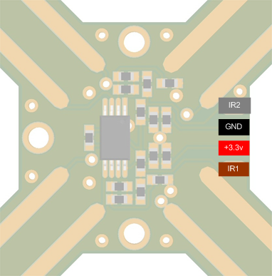
Pinout

Pinout
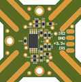
| Pin # | Name | Type | Description | Suggested Color |
|---|---|---|---|---|
| 1 | IR2 | OUT | IR Signal Axis 2 | Grey |
| 2 | GND | PWR | Ground | Black |
| 3 | VCC | PWR | +3.3v Power Supply | Red |
| 4 | IR1 | OUT | IR Signal Axis 1 | Braun |
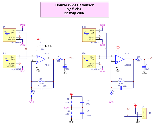
Schematic

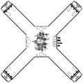
PCB
Top copper side
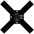
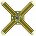
Bottom copper side
Top components details


Gerber & Drill Files
download IR double wide sensor board gerber & drill files (zip)
RS274X, units = Inches, format = 2:5
- IR_double_wide.GTO (Top Component Print Layer)
- IR_double_wide.GTS (Top Solder Mask)
- IR_double_wide.GTL (Top Copper Layer)
- IR_double_wide.GBL (Bottom Copper Layer)
- IR_double_wide.GBS (Bottom Solder Mask)
- IR_double_wide.DRI (NC XY coordinates & Drill tools sizes)
Possible PCB Manufacturers
Assembly
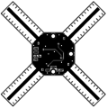
Components Layout
Top components Layout
Top components Layout (zoom)
Top components details


Bill Of Material
under construction
Downloads
Source files
Gerber & Drill files
Assembly files