Difference between revisions of "Infrared Double Wide Sensor Board"
Jump to navigation
Jump to search
(→Pinout) |
(→PCB) |
||
| Line 31: | Line 31: | ||
<gallery> | <gallery> | ||
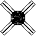
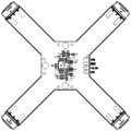
Image:IR_double_wide_Top_Copper.png| | Image:IR_double_wide_Top_Copper.png|Top copper side | ||
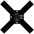
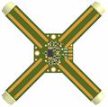
Image:IR_double_wide_Bottom_Copper.png| | Image:IR_double_wide_Bottom_Copper.png|Bottom copper side | ||
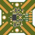
Image:IR_double_wide_Top_Components.png|Top components details | Image:IR_double_wide_Top_Components.png|Top components details | ||
</gallery> | </gallery> | ||
Revision as of 10:20, 28 March 2008
Overview


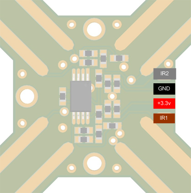
Pinout

Pinout
| Pin # | Name | Type | Description | Suggested Color |
|---|---|---|---|---|
| 1 | IR2 | OUT | IR Signal Axis 2 | Grey |
| 2 | GND | PWR | Ground | Black |
| 3 | VCC | PWR | +3.3v Power Supply | Red |
| 4 | IR1 | OUT | IR Signal Axis 1 | Braun |
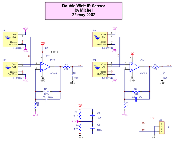
Schematic

PCB
Top copper side
Bottom copper side
Top components details


Gerber & Drill Files
under construction
Possible PCB Manufacturers
Assembly
Components Layout
Top components Layout
Top components Layout (zoom)
Top components details


Bill Of Material
under construction
Downloads
under construction