Sensors/IMU
See the IMU subsystem page for the software drivers.
Terminology
- IMU: inertial measurement unit: only measures the accelerations and rotation rates (and magnetic field)
- AHRS: attitude and heading reference system: uses IMU data + extra (airspeed/GPS/baro/...) to do sensor fusion and provide pitch and roll
- INS: integrated navigation system: uses IMU + Navigation sensor(s) (e.g. GPS) + even more complex algorithms that besides pitch and roll also interpolates positions and velocities using the attitude corrected acceleration measurements.
Paparazzi IMUs
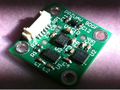
Booz IMU v 1.01
- High quality analog devices sensors
- 16bit ADC capable of 200 000 samples per second
- Special attention to clean power with onboard linear supplies
- Efficient high-speed SPI for minimal microcontroller overhead and ultra-low latency (=better controller performance).
- Fits on Booz, Lisa AND Tiny/TWOG autopilots.
While originally designed for use with rotorcrafts, code is now available for use with fixed wing.

The hardware description is here.
Available at PPZUAV.
YAI v1.0
Why "yet another imu" while there are already so many out there?

- Designed to be completely compatible with original booz IMU and its code
- Cheaper sensors (lower bias stability)
- Higher resolution (16bits) and frequency (200ksps) and cleaner onboard power supply, better grounding and shielding than compared with e.g. external sparkfun breakout boards
- Fast low latency SPI communication (no uart as the tiny/twog miss uarts)
- The most important part of attitude determination is proper kinematic compensation using for instance GPS, pressure sensors etc etc. When using IMU with external processors there is often less flexibility. Things as timing for instance are as important as the quality of the gyros themselves.
Board, BOM -> [ http://svn.savannah.nongnu.org/viewvc/paparazzi-hardware/trunk/sensors/yai/?root=paparazzi Hardware Repository]
Aspirin IMU

Next generation flat imu. This little imu with latest generation of integrated high rate high resolution gyros's moreover has very low noise and stable power supplies and outputs all sensors interrupt pins for optimal performance.
Note: while the main intended use is the very low latency high performance spi+i2c+interrupts connection (e.g. on lisa/M), please note that aspirin v2 can also be used with any tiny/twog for fixedwing aircraft with the same 4-wire interface and identical software as the PPZUAV-IMU. (connect Aspirin-SCK and aspirin-SCL to the I2C-SCL, aspirin-mosi and aspirin-SDA to I2C-SDA, Vcc to 5V (preferably linear), aspirin-gnd and aspirin-miso to GND, and aspirin-CS to 3.3V.)
Detailed information about the Aspirin IMU is available here.
KroozSD
The KroozSD has it's IMU(MPU6050(Gyro/Accel), HMC5883(Mag), MS5611(Baro) already on the board. The Files for the Krooz IMU are currently only in the "Kooz port of the paparazzi master branch" available. port of the master branch
3rd Party IMU
Loose Terminology Note: Like the sparkfun website, the following text incorrectly equates the term "degree-of-freedom" with sensor measurement. Unless we're talking about articulated arms (which paparazzi to date isn't involved with), a body can only have 6 physical DOFs and that would correspond to translation and rotations in the x,y,z Cartesian directions of 3D space. If the vehicle state vector includes positions and velocities for each degree of freedom, the state vector would have a dimension of 6 x 2 = 12 states. The goal is to reconstruct these vehicle states using sensor measurements, as once the states can be obtained with reasonable certainty, a control algorithm can have a shot at controlling the system. Using various filtering techniques, multiple sensor types can be combined to estimate these states.
IMU's measure rotation rates, acceleration (6DOF) and some also magnetic fields (9DOF). This data is used by an autopilot to estimate the state of the aircraft. They that can be used with a Paparazzi autopilot based UAS. If you happen to have such a device, we really would love to see that you share your IMU paparazzi autopilot integration projects information on this Wiki.
PPZUAV IMU 9DOF
9DOM IMU
Example Wiring to Tiny2.11
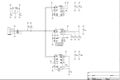
Schematic


Another IMU based around the ITG-3200, ADXL345 and HMC5843.
Features: I2C out 5v input. Interrupts .
PCBs available from PPZUAV (assemblies soon). Schematic open, design is Altium Designer, gerbers available.
A sample airframe illustrating all calibration issues and reading and merging the sensor at 100Hz with minimal control delays is in the repository to get you started:
airframe: PPZUAV/fixedwing/tiny_imu.xml
settings: tuning_basic_ins.xml
telemetry: default_fixedwing_imu.xml
Credit and thanks go out to Christophe for making the code and testing.
Media
YouTube: http://www.youtube.com/watch?v=OaMTyJ-s-PU
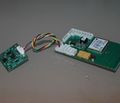
Ryan Mechatronics CHIMU AHRS
Very nice product: using the ultra high speed ultra low latency 200Hz SPI-slave mode (even 200Hz innerloop control of fixedwing is possible) or simple 4-wire connection via serial port to any TWOG/TINY/LISA/YAPA.
Don't want to spend time testing AHRS filters? Nor calibrating IMU? This module with molex connector can be bought calibrated and does all the filtering internally.
Use it with highspeed SPI on LPC-based boards: http://www.youtube.com/watch?v=mxx-f3Ur0L8
 <modules>
   <load name="ins_chimu_spi.xml" />
 </modules>
...
<subsystem name="spi_slave_hs"/>
Use CHIMU with simple uart connection on both lisa or tiny/twog
 <modules>
   <load name="ins_chimu_uart.xml">
     <configure name="CHIMU_UART_NR" value="0"/>
   </load>
 </modules>
SparkFun Razor 6DOF IMU
This product has been discontinued by the manufacturer !


6DOF - Ultra-Thin IMU
Very cheap, currently 62-72 Euro. Shop in Europe
Has been integrated in Paparazzi by implementing the DCM algorihm from William Premerlani and Paul Bizard by Hochschule Bremen, Germany.
Remove the high pass filters of the RazorIMU to get better results.
For the Twog and Tiny 2.2 autopilots you have also remove the resistors to GND and the series resistors to the MC of the 5V analog inputs. The code to fly normal plane is currently in the repository. Christoph is working on improvements look here: http://paparazzi.enac.fr/wiki/User:Christoph
Connections and wiring to the tiny13
Drotek 6DOF (MPU6050)


IMU Drotek MPU6050 6 Degrees of Freedom Invensens MPU6050
Tiny, very low cost 12 € , 5V and 3.3V input, I2C interface.
Note that this sensor use the alternative I2C address. Correct is in the driver file. It is a low cost and precise solution for normal aircraft.
Similar chinese breakout boards can be found on ebay starting at 2€.
Drotek 10DOF (MPU6050-HMC5883-MS5611)


IMU Drotek MPU6050 - 10 Degrees of Freedom
Tiny, low cost 23€, 5V and 3.3V input (onboard voltage regulator), I2C interface. It is a low cost and precise solution for normal aircraft with a excellent baro sensor.
By default the axes orientation should be as printed on the pcb, meaning z-axis pointing down if ICs are facing down. The orientation can be switched so that the IMU can be mounted ICs facing up by defining IMU_DROTEK_2_ORIENTATION_IC_UP.#
Maybe setting a different I2C address is required.
| File: conf/airframes/myplane.xml |
  <subsytem name="imu" type="drotek_10dof_v2">
    ...
    <configure name="DROTEK_2_I2C_DEV" value="i2c0"/>
    <!--define name="DROTEK_2_MPU_I2C_ADDR" value="MPU60X0_ADDR" /-->
    <define name="IMU_DROTEK_2_ORIENTATION_IC_UP" value="1" />
  </subsystem>
|
To read the baro use the separate baro_ms5611 module.
Similar chinese breakout boards (different pinout/pcb size) can be found on ebay starting at 12€.
SparkFun SEN-10121

IMU Digital Combo Board - 6 Degrees of Freedom ITG3200/ADXL345
http://www.sparkfun.com/products/10121
Tiny, ADXL345 accelerometer, ITG-3200 gyro, 3.3V input, I2C interface.
This IMU has been tested and flown with Tiny v2.11 and TWOG. It is very similar to the PPZUAV IMU.
Details of configuration.
Pololu MinIMU-9
This product has been discontinued by the manufacturer !

IMU Digital Combo Board - 9 Degrees of Freedom L3G4200/LSM303
http://www.pololu.com/catalog/product/1265
Tiny, LSM303 accelerometer and magnetometer, L3G4200 gyro, 3.3V input, I2C interface.
This IMU has been tested and flown with TWOG.
Details of configuration.
Cloudcap Crista IMU

Official website / Site not found !
More infos soon.
3rd Party INS
INS measure rates with their sensors and run algorithms to estimate the state on their own. They give this information the the autopilot (e.g. Euler angles) that can then use it for navigation.
ArduIMU+ V2 (Flat)

- 3 axis accelerometer + 3 axis gyroscope
- Low cost
- Has been integrated in Paparazzi by ZHAW, Winterthur, Switzerland.
- A magnetometer has been integrated in the software to compensate drift in yaw.
- GPS data from the Tiny is passed over I2C to the AHRS on the IMU.
- Is sold by Sparkfun and DIYDrones Store.

There is a module for this AHRS (ins_vn100.xml for fixedwings).


Official website Rugged version Official website SMD version
Vectornav VN-200 is a relatively new (2015) INS solution. In our tests it outperforms GX2/3 and has similar performance as MTI-G (see white paper A Comparison of Flight Data from 5 Small Low-cost IMUs from Nathan V. Hoffer, Calvin Coopmans, Austin M. Jensen, AggieAir at the Utah Water Research Laboratory) at roughly half price.
The code is available, use it as an INS subsystem (ins_vectornav). Comes with recommended configuration target (setup_vectornav) so it can be easily configured. Another option is to use the Windows configuration tool from Vectornav.
Recommended Vectornav configuration is recorded in this table. In the future there could be a configuration module as a part of paparazzi, for the time being an external configuration tool is required (it is provided in sw/tools/vectornav_configurator).
MicroStrain 3DM-GX2/3

Official website GX2 Official website GX3
GX3 AHRS (ahrs_gx3.xml) available for both fixedwing and rotorcraft. Can be used for GX2 too, since the commands and packets are identical (GX2 has slower update rate).
Xsens MTi and MTi-G (with GPS)


In sensor fusion, calibration and timing are crucial. If you want latency compensated ADXRS gyro integrated attitude done by an efficient and optimized Blackfin DSP you need an XSens. For rotorcraft the 100Hz is a bit slow, but for fixedwing it's perfect. Directly compatible with Yapa and Lisa and all needed code in paparazzi.
MemSense MAG3
MAG3 - 6 DOF Analog IMU with Triaxial Magnetometer
The Very Short Essential Introduction To Inertial Attitude Estimation
The only physical entity related to attitude (pitch and roll) is the earth gravity vector (unless you use a multi-antenna phase-measuring GPS... $$$$). Unfortunately, the sensors that measure gravity (=accelerometers) also measure so-called kinematic accelerations or in other words: changes in speed: like centrifugal forces, Coriolis forces, linear accelerations etc... The sum of all these litteraly is "what you feel" and is called "specific force".
so
accelerometer_value (specific force) = earth_gravity + change in velocity (linear accelerations) + velocity times turn rate (centrifugal etc)
or
A = B + C + D
You measure A and want to know B. What all "gyroscopes and accelerometer only" AHRS projects are doing in some way or another is to neglect the last 2 (C and D). In many situations this is not bad: for instance: when testing the AHRS attached to your computer: it can not accelerate for a very long time (at most a few meters: so if you accelerate to the left, then you need to accelerate to the right directly after so the average is zero) and can not rotate to much either (or your cable gets strangled). This is why all AHRS videos on Youtube look perfect. And on the desk they are perfect: you neglected 2 terms in the equation that in that situation are perfectly neglect-able. Also with a quadrotor that hovers and keeps its nose in the same direction all the time, these neglected terms are small.
Now what about the gyroscopes you might ask. I deliberately keep them only second as gyroscopes (turn rate or rotation speed sensors) do NOT give you attitude but ONLY HELP TO SOLVE SHORT TERM errors in the previous part. If gyroscopes would measure turn-rate perfectly, then they would help more but all MEMS/PIEZZO sensors are more or less sensitive to 1) temperature, 2) turnrate, 3) vibrations, 4) accelerations, 5) radiation, 6) power supply quality 7) non-linearity 8) ADC-quality 9) dynamic range and saturation problems, ... so if you integrate gyroscopes, sooner or later errors build up (drift). I put this list here so you know what to pay attention for: if using gyroscopes: always try to keep the temperature as constant as possible or let the temperature settle, reduce vibrations (dampers), use better ADC (e.g. 10bit ADC with +/- 1200 deg/sec gyros have a resolution of 2.4 degrees/s per ADC tick, so your phi/theta might drift 1.2deg/sec without noticing) and power supply filtering and shielding etc to start with. All of these define for how long (seconds!/minutes?) gyroscope integration is useful.
If you convert the accelerometer directly to attitude and plot it, it will vibrate a lot and will show errors when you accelerate the AHRS on your desk. During a coordinated turn of a fixedwing plane, the force you feel is perpendicular to the plane (not pointing to earth). The accelerometer only clearly is insufficient to know your attitude. One solution is to use gyroscopes that are so good that you can predict for many minutes (then the average acceleration during several turns would still point to earth). But if your gyros can only help for shorter terms (like all MEMS sensors of less than 500euro/each) then extra information is required. E.g: if you add GPS data or airspeed data however, from the flightpath you can quite accurately reconstruct the missing C and D terms. Together with the accelerometer you can know "where the earth is" even when you keep accelerating and turning. Here questions like latency, update rate, noisy derivatives (linear acceleration) are of importance.
Finally there is the heading... GPS ground-track is not the same as nose direction. Gyroscopes measure how much the nose has been turning, so using GPS to correct it induces errors that increase with crosswind. Magnetometers can help here, and become necessary whenever you do not move enough anymore (hovering). This situation can also occur in plane flying in very strong winds.
See the AHRS subsystem page for an overview of some algorithm implementations.