ImuCalibration
Theory
Accelerometer and Magnetometer calibration is critical to AHRS performance and can be performed using no special hardware. For Gyrometer calibration you need a very good turnable. For the magnetometer, it is very important that the calibration be performed in the fully assembled vehicle, with all systems powered on. This is called hard-iron calibration and will allow us to compensate for any constant parasitic magnetic fields generated by the vehicle. The calibration process consists of finding a set of neutrals and scale factors for each sensor, such as

The principle of the calibration is the following: an accelerometer, on a vehicle at rest, measures a constant vector (the opposite of gravity) in the earth frame, expressed in the vehicle frame.

DCM is a rotation matrix that converts between earth frame and body frame. It will change when we change the orientation of the vehicle. Nevertheless, a rotation conserves the norm of a vector. We can thus obtain the following scalar equation that doesn't depend on the vehicle orientation :

Where 9.81 is earths average gravity value
We can then record an important number of measurements in different orientations and find the set of scale factors and neutrals giving the norm closest to the average gravity value
How It Works
- It first makes an initial guess using min and max, i.e. for each axis
- neutral = 0.5 * (max + min)
- sensitivity = 0.5*(max - min)
- It then uses a data fitting algorithm to optimize the initial guess.
Screenshot of Scilab version.

But before any calibration it is of utmost importance the signs and the axis of your sensors are correct!. Therefore make sure and adjust where needed the axis signs of your IMU are correct. To do so, the steps outline in "Finding and Checking Signs" are needed first.
Finding and Checking Signs
For supported IMUs, the correct default signs are already defined in the code.
If using a new IMU or sign for yours are not in the code yet, here is the way to find them.
We're calibrating everything relative to the IMU frame - Paparazzi has a parameter to define the orientation of the IMU with respect to the body of the vehicle that we'll use later, once you'll have decided of a good mechanical mounting.
Paparazzi uses North East Down (NED) frame, that is positive x is pointing to the front, positive y to the right and positive z down.
Accelerometer:
An accelerometer measures the non gravitational acceleration, that is . is pointing down, so is pointing up. So stop moving, disregard earth rotation and you'll measure .


- When your IMU is level you should see x=0 y=0 z=-9.81
- When pitching up -g is aligning with x, so you should see x>0, y=0 and z<0
- When banking left -g is aligning with y, so you should see x=0, y>0 and z<0
Magnetometer:
A magnetometer measures the Earth's magnetic field. In the northern hemisphere, this points north and down and in the Southern hemisphere north and up.
Thus in the northern hemisphere:
- When you align your IMU with the direction of north, you should see x>0, y=0, z>0.
- When pitching the IMU down, the magnetic vector is aligning with x, so x should increase and z should decrease to zero.
- If yawing your IMU to the left, the magnetic vector is aligning with y, so y should be positive, x should decrease to zero and z stay positive.
And in the southern hemisphere:
- When you align your IMU with the direction of north, you should see x>0, y=0, z<0
- When pitching the IMU up, the magnetic vector is aligning with x, so x should increase and z should increase towards zero.
- If yawing your IMU to the left, the magnetic vector is aligning with y, so y should be positive, x should decrease to zero and z stay negative.
This also means that after calibration, your mag should report the same values as your normalized local magnetic field when placed horizontally and pointing north.
Gyrometer:
You need some turntable to calibrate the scale factors of your gyros. For signs, the definition of the frame gives the following properties:
- When rolling right, should be positive.
- When pitching up, should be positive.
- When yawing to the right, should be positive.


Verification:
Switch to AHRS telemetry mode and look for the fields that are prefixed with imu_
- Bank right should give positive phi
- Pitch up should give positive theta
- Yaw right should give increasing psi
- The value you'll see after letting the IMU rest will end up being the "measure" (that is accelerometer and magnetometer.) If those are wrong, the problem is in the calibration of your sensors.
- The values you get while moving the IMU are influenced by the gyros. If what you see is the value going crazy when you move and then stabilizing to something good after you stop moving, the problem is in your gyros.
If all is done for the axis and coreect signs, one can proceed to the calibration steps.
Calibration Script Installation
Vital scripts and places:
- Python script to calibrate the accelerometers and magnetometer. The application can be found in the Paparazzi directory under: sw/tools/calibration/calibrate.py
- Before you start calibrating one could clear log directory (PAPARAZZI_HOME/var/logs), it can greatly simplify log file search process. However an ll command will per default show a list of log file in date order, where the last one is mostly the file you need for the calculation process.
Also for the calibration helper application to work, you need additional Python libraries. If you already have the package paparazzi-dev installed, the needed libraries were already installed as dependencies. If this is not the case you need to install python-scipy and python-matplotlib. This can be done via Synaptic Package Manager or via the command-line of Ubuntu.
$ sudo apt-get install python-scipy
$ sudo apt-get install python-matplotlib
How to Calibrate Your IMU
Basic procedure:
- Flash the board with your normal AP firmware if you did not already did that before.
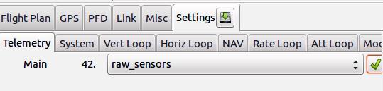
- Switch to the "raw sensors" telemetry mode via GCS->Settings->Telemetry and launch "server" to record a log.
- Rotate your IMU/airframe into different attitudes to record relevant measurements for each axis.
- It is important that you get the min/max sensor values on each axis!
- Stop the server application after you are done with callibrating, it will write the log file buffer (to var/logs).
- Run the Python script on it to get your calibration coefficients
- Add the on screen displayed values to your airframe file, one can also use a copy/paste.
- See details/examples for specific sensors below.
- If you have data from more than one aircraft in your logfile, you will need to specify the aircraft id via the --id option.
It can be found in the Paparazzi Center upper left side. (first comes A/C name, and then id value)

Run the script with --help to list available options:
sw/tools/calibration/calibrate.py --help
Calibrating the Accelerometers


TIP: Since accelerometers are very sensitive to vibration distortions, strap your IMU board tight to some heavy object like a big battery. It will help keep the board steady while rotating.
Once your decided to calibrate; take the steps with great care. If not done as precise as you possibly can, than factory calibration values are even better than a poorly calibrated accelerometer.
Here you start to calibrate the accelerometers:
turn and hold the IMU on all six sides of the 'cube' for 10 seconds per IMU axis:
- upright
- inverted
- on the nose
- on the tail
- on the right side
- on the left side
Please note that we talk about the IMU axes here, and not the airframe axes.
So if you have your IMU mounted under a specific angle in your aircraft; make very sure you align the axis of the IMU and not the aircraft axes with earth's gravity. Also for the accelerometer calibration the IMU can, but does not need to be mounted inside the airframe. Only the calibration of a magnetometer must be performed while in your aircraft.
You can also take some measurements banking 45 degrees.
Try to get a homogeneous distribution of your measurements. It is better to let the aircraft rest while measuring an axis to avoid inaccuracies from shaking the IMU in your hand.
Then stop the server so it will write the log file which must containing the needed IMU_ACCEL_RAW message values. Then run the Python script using the just newly generated log data as the source to get your calibration coefficients:
Open a terminal window and run:
sw/tools/calibration/calibrate.py -s ACCEL var/logs/YY_MM_DD__hh_mm_ss.data
Where YY_MM_DD__hh_mm_ss.data is the name of the log data file that was just generated.
Add the resulting output values from this script to the airframe file in the section IMU, for example:
| File: conf/airframes/myplane.xml |
 <section name="IMU" prefix="IMU_">
   ...
   <define name="ACCEL_X_NEUTRAL" value="46"/>
   <define name="ACCEL_Y_NEUTRAL" value="12"/>
   <define name="ACCEL_Z_NEUTRAL" value="175"/>
   <define name="ACCEL_X_SENS" value="4.90862760829" integer="16"/>
   <define name="ACCEL_Y_SENS" value="4.9043976463"  integer="16"/>
   <define name="ACCEL_Z_SENS" value="4.82837916573" integer="16"/>
   ...
 </section>
|
Calibrating the Magnetometer
First of all it is important to know that all ferromagnetic materials near the magnetometer distort the measurements. So preferably you do the magnetometer calibration with the magnetometer and autopilot mounted fixed in your airframe. Also keep your airframe as far away from metal and magnets as possible.
Calibrating for the Earth magnetic field
The most crucial part for the magnetometer calibration:
Steps:
- Slowly spin your aircraft around all axes
Ideally you would spin it around all axes until you have densely covered the whole sphere with magnetometer measurements. Take a look at figure MAG2 on how that would look like.
Optional method
If this rotation of your whole airframe is to hard to do: One could also just make sure to really get the min/max on each axis by aligning the magnetometer axes along the local magnetic field vector:
- Calculate the inclination and declination of the magnetic field where you live that can be looked up here. Just put in zip/country+city/coordinates & date to get proper degrees. See MAG1 figure.
- Now point the each mag axis in the direction you got from previous step.
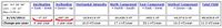
fig. MAG1 - An example for London
TIP: It can also be convenient to plot the IMU_MAG_RAW values to see when you get the maximum on each axis.
- Launch Paparazzi Center->Tools->Realtime_Plotter and Tools->Messages
- Drag&Drop each axis of the IMU_MAG_RAW message to the Plotter canvas.
After you took all measurements, stop the server so it will write the log file and run the Python script on it to get your calibration coefficients:
sw/tools/calibration/calibrate.py -s MAG var/logs/YY_MM_DD__hh_mm_ss.data -vp
Where YY_MM_DD__hh_mm_ss.data is the name of the log data file that was just generated.
The -v parameter turns on verbose mode, -p turns on 3D plotting of the results. You can omit them if you don't want this.
This basically does a hard-iron (i.e. offset of the sphere) and soft-iron (i.e. distortion to an ellipsoid) calibration. You can see an example result in Figure MAG2.
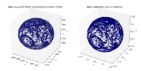
fig. MAG2 - Measurements fitted to ellipsoid

The magnetic field strength and axis are different depending on where you are in the world, because of this you have to set the local magnetic field of the location you intend to fly. Only if you are using the older euler filter you have to recalibrate your magnetometer to fly somewhere else on the planet.
Calibrating for Current
When your aircraft flies, currents are flowing through all the electrical wires in your aircraft. These currents induce a magnetic field. This can create an offset in the measurement of the magnetic north. That is not what we like to have. Luckily we can compensate for this unwanted side-effect by adding current compensation values to the airframe file. This calibration is mainly interesting if you have an aircraft with electric engine.
TIP: This interference effect can also be reduced by putting the magnetometer somewhere away from power wires and by twisting power wires together.
Before doing this calibration, it is important to disengage any autopilot autonomous control and put it in RC control only mode.
Steps:
- Set up a current sensor in Paparazzi, or define MILLIAMP_AT_FULL_THROTTLE in your airframe file to enable a current estimation.
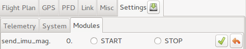
- Load the send_imu_mag_current.xml module.
- Start the send_imu_mag_current module via settings
- Put your aircraft on the ground and make very sure to hold it steady, movement will mess up the calibration
- Slowly ramp up the throttle
- Stop the server

Now the log data is written to log file and we need to do something with it
Open a terminal and just run the script by entering:
sw/tools/calibration/calibrate_mag_current.py var/logs/YY_MM_DD__hh_mm_ss.data
Add the resulting output values from this script to the airframe file in the section IMU, for example:
| File: conf/airframes/myplane.xml |
 <section name="IMU" prefix="IMU_">
   ...
   <define name= "MAG_X_CURRENT_COEF" value="0.0591913538739"/>
   <define name= "MAG_Y_CURRENT_COEF" value="-0.132912120794"/>
   <define name= "MAG_Z_CURRENT_COEF" value="-0.0724604582039"/>
   ...
 </section>
|
Re-compile and upload your airframe again.
You can check if the calibration worked by watching the psi angle as you ramp up the motors while holding your UA steady. Be sure to do this without the control system active.
Note that a change in you airframe configuration, e.g. other gains make the motors spin faster, or the wiring will require a full new current calibration!
Calibrating the Gyrometer
To calibrate the gyrometer you need a turntable, take a look here to see how such a setup would look like and which steps are involved. There is a dedicated page for this procedure since the steps are not trivial to perform.
Note that gyrometer neutrals a.k.a. bias, are usually not a problem, since they are set by the AHRS aligner at each startup and some AHRS algorithms continuously estimate the bias during flight.
Calibrating Infrared Sensors
Just in case you still use IR piles for attitude estimation, which is not so common in the days of cheap and available MEMS sensors the steps below will clarify:
Put the aircraft in a styrofoam container or completely seal the IR sensors with styrofoam or similar blocks and get a reading of the neutrals for each axis. Also take the gyro neutrals at this time. Update your airframe file, flash the AP and re-check the neutrals.
Using the roll gyro as a worked example: Run up your GCS and ensure it is communicating with your airframe. Make sure your airframe is roughly level and that it cannot move. Now run the Messages Tool and the real time plotter tool. The messages tool will have lots of flashing lights indicating when it receives various telemetry packets. In the Messages tool, Click on Gyro Rates and you should see a list of variables. Click on Roll_ADC and drag and drop in onto the main window of the Real Time plotter. Now give it a while to build a stable graph.
Once things have been running this way for a while, in the Real Time Plotter, click on Curves in the menu and select the 1:telemetry:GYRO_RATES:Roll_ADC entry. As you select it, you should see the average and standard deviation values. We need the average value. Jot down the number you have. I have -24.536.
Now go edit your airframe file and look for the ADC_ROLL_NEUTRAL value. In my airframe file the value is 520. As my average value from the Plotter is a negative figure, it indicates that the roll Neutral is too high, subtract the average value from the present setting. So I edited my airframe file to be 495.464 (520-24.536).
Recompile and reflash (Don't worry about restarting the GCS, The messages program or the other running processes - they will catch up just fine after flashing). Once the Board is back up and the plotter continues, reset it from the menu to get rid of the average. Watch it for a while and check that the line and acculmulated average is on or around 0. You are done. Use the same process for the IR sensors!