ImuCalibration/Gyroscopes
Turntable Procedure
Hardware
Pictures
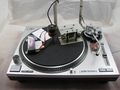
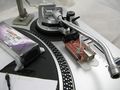
Turntable rig
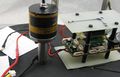
IMU cradle view 1.0
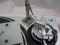
IMU cradle view 1.1
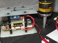
Encoder mount base
Olimex LPC H2148
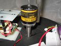
Omron rotary encoder


Components
- audio-technica AT-LP120_USB Direct Drive Professional Turntable
- Olimex LPC H2148
- Omron rotary encoder
- Lisa/L+IMU, Xbee 2.4Ghz modem set, fibreglass mounting plates and general wiring components
- Encoder mount hoop - engineering shop?
Wiring
Encoder to LPC
- Black (common) to EXT2 GND
- Red 5~12 VDC to EXT2 Vin(5v)
- White OUTA to EXT1 PO.22
LPC to LPC
- EXT2 3.3v to EXT1 PO.22 (pull up resistor)
Software
LPC Code Modifications
In case of USB 2.0 A-B cable operation, ~/conf/airframes/Poine/turntable.xml has to be amended, as follows, and saved as ~/turntable_dev_usb.xml:
| File: conf/airframes/Poine/turntable_dev_usb.xml |
 main.CFLAGS += -DUSE_USB_SERIAL
 main.srcs += $(SRC_ARCH)/usb_ser_hw.c
 main.srcs += $(SRC_ARCH)/lpcusb/usbhw_lpc.c $(SRC_ARCH)/lpcusb/usbinit.c
 main.srcs += $(SRC_ARCH)/lpcusb/usbcontrol.c $(SRC_ARCH)/lpcusb/usbstdreq.c
 main.CFLAGS += -DDOWNLINK -DDOWNLINK_TRANSPORT=PprzTransport -DDOWNLINK_DEVICE=UsbS

 #main.CFLAGS += -DUSE_UART0 -DUART0_BAUD=B115200
 #main.srcs += mcu_periph/uart.c
 #main.srcs += $(SRC_ARCH)/mcu_periph/uart_arch.c
 #main.CFLAGS += -DDOWNLINK -DDOWNLINK_TRANSPORT=PprzTransport -DDOWNLINK_DEVICE=Uart0

 main.srcs += subsystems/datalink/downlink.c subsystems/datalink/pprz_transport.c

 #main.CFLAGS += -DMB_TACHO
 #main.srcs += $(MB)/mb_tacho.c

   </makefile>

 </airframe>
|
A new turntable session has to be added to ~/conf/control_panel.xml:
| File: conf/control_panel.xml |
   <session name="Flight with USB-serial_TT modem">
      <program name="Data Link">
        <arg flag="-d" constant="/dev/ttyACM0"/>
        <arg flag="-nouplink" constant=""/>
        <arg flag="-s" constant="115200"/>
      </program>
      <program name="Server"/>
      <program name="GCS"/>
    </session>
|
A new aircraft (A/C) named "TT" has to be built using the paparazzi centre:
| File: conf/conf.xml |
   <aircraft
   name="TT"
   ac_id="3"
   airframe="airframes/Poine/turntable_dev_usb.xml"
   radio="radios/cockpitSX.xml"
   telemetry="telemetry/default_rotorcraft.xml"
   flight_plan="flight_plans/dummy.xml"
   settings=" settings/rotorcraft_basic.xml"
   gui_color="blue"
  />
  <aircraft
|
IMU Code Modifications
Similar files have to be created for the IMU cradle unit:
| File: conf/control_panel.xml |
   <session name="Flight USB-serial_TT @57600">
      <program name="Data Link">
        <arg flag="-d" constant="/dev/ttyUSB0"/>
        <arg flag="-s" constant="57600"/>
      </program>
    </session>
|
The airframe is a standard rotorcraft file with the appropriate IMU defined.
| File: conf/conf.xml |
   <aircraft
   name="TTIMU"
   ac_id="4"
   airframe="airframes/Audax/slh_lisa_mkk_i2c_indoor_tt_asp1.0.xml"
   radio="radios/cockpitSX.xml"
   telemetry="telemetry/default_rotorcraft.xml"
   flight_plan="flight_plans/rotorcraft_basic.xml"
   settings=" settings/rotorcraft_basic.xml"
   gui_color="blue"
  />
  <aircraft
|
Encoder Code Modifications
Line 43 in ~/sw/airborne/firmwares/motor_bench/main_turntable.c has to be amended to reflect the encoder's factory pulses per revolution (P/R) setting from default "#define NB_STEP 256". The encoder above has a factory resolution set at "300" (P/R). The resolution setting has to reflect turntable velocity message outputs of ~200deg/s (3.49065rad/s) and ~270deg/s (4.71239rad/s) for 33rpm and 45rpm respectively.
| File: sw/airborne/firmwares/motor_bench/main_turntable.c |
#define NB_STEP 300
|
Calibration Session
Data Collection Setup
In Paparazzi Centre:
- Build A/C "TT" using "main" target and the USB A-B lead detached from PC.
- Attach USB A-B lead to both LPC & PC and upload code.
- Start "Flight with USB-serial_TT modem" "Session".
- Open default "Message" box and "Real-time Plotter" from the "Tools" menu. Choose "IMU_TURNTABLE" readout.
- Switch to A/C "TTIMU" in same "Paparazzi Centre" window. Build and upload code.
- Start "Flight USB-serial_TT @57600" "Session".
- In original "GCS" window change "Telemetry" to "raw_sensors".
- Open a new "Message" box and choose "IMU_GYRO_RAW" readout.
- Arrange placement of IMU cradle, for the chosen axis (p, q, r), on the side which reports the highest or positive reading.
- Start turntable @ 33rpm and drag "IMU_TURNTABLE" data from "Message" box to "Real-time Plotter".
- Restart "Server" 1 second before a full minute readout and record for four minutes.
- Halt "Data Link" for both A/Cs "TT" and "TTIMU" and change turntable speed to 45rpm.
- Restart - click both "Data Link" boxes and record for a further four minutes.
- Stop "Server".

Data Analysis
- The captured turntable velocity and gyro axis data can be found date and time stamped at:
| File: var/logs/xx_xx_xx__xx_xx_xx.data |
~/var/logs/12_06_05__18_11_00.data
|
- Right click the file and open with "LibreOfficeCalc". Click column D and elect "Sort Ascending".
- Choose "Extend selection" box. Note the time stamps of the IMU_TURNTABLE outlier data in column A.
- Insert them in the search box of a separate open editor version of the log file and delete the offending prints.
- Save the file and run the following:
| File: ~/paparazzi/sw/tools/calibration$ |
    ./calibrate_gyro.py --id 4 --tt_id 3 --axis r /home/stephen/paparazzi/var/logs/12_06_05__18_11_00.data

     Linear regression using stats.linregress
     regression: a=824.56 b=16.03, std error= 0.048
     <define name="GYRO_X_NEUTRAL" value="16"/>
     <define name="GYRO_X_SENS" value="4.967519" integer="16"/>
|
- These accompanying plots are also generated:
