Advanced Navigation Routines
Introduction
The flight plan standard navigation functions are very flexible. However sometimes one needs to perform a very specific task, and the basic functions are not enough to accomplish a special mission. In that case you can use additional modules functions in the flight plan. By adding a navigation capability to your airframe. The flight plan now has extra functionality that can be used.
Thanks to Team OSAM's contribution these navigation capabilities have been added.
To use these navigation routines, you need to change the navigation subsystem type to extra in your airframe file. The navigation extra subsystem includes extra navigation routines like OSAMnav, spiral, poly_survey_advanced, nav_cube, etc.
<subsystem name="navigation" type="extra"/>
Also include OSAMNav.h in your flight plan:
#include "subsystems/navigation/OSAMNav.h"
NOTE The latest version of PaparazziUAV (v5.10 is the one I am using at the moment) does not have the OSAM navigation contributions as a subsystem but a module. It can be found in the link mentioned below. Not sure from which version the changes apply, but if you cannot find the header file in the subsystems folder, it is most probably in the modules folder.
sw/airborne/modules/nav
Flower

The flower navigation routine flies the aircraft in a flower pattern defined by two waypoints. The center waypoint defines the center of the flower and the altitude the plane flies at. The edge waypoint defines the radius of the flower.
In our example the waypoints are called "Center" and "Edge":
| File: conf/flight_plans/myflightplan.xml |
  <waypoint name="Center" x="-20.0" y="-160.0"/>
  <waypoint name="Edge" x="-10.0" y="-60.0"/>
|
Then you can add flower to your flight plan:
| File: conf/flight_plans/myflightplan.xml |
  <block name="Flower">
    <call fun="InitializeFlower(WP_Center,WP_Edge)"/>
    <call fun="FlowerNav()"/>
  </block>
|
Note that in the function InitializeFlower the waypoints need the prefix "WP_".
Bungee Takeoff
The bungee takeoff routine helps to automate takeoff by turning the throttle on after the bungee has been release from the hook. The only waypoint you need for this routine is the position of where the bungee is pegged to the ground. Using this waypoint, a line is drawn from the position of the aircraft to the bungee waypoint. This line is called the launch line and will stop updating once the speed of the plane exceeds the MIN_SPEED. This allows the user to initialize the routine, move the plane and launch it without having to reinitialize. Once the plane is launched, it will follow the launch line until it crosses the throttle line. The throttle line is a line perpendicular to the launch line at a distance d from the bungee waypoint (see the diagram below). When the plane crosses the throttle line and the speed of the aircraft is greater than MIN_SPEED, the throttle comes on. After the throttle comes on, the plane keeps going straight until it reaches a specified speed and altitude above the bungee waypoint altitude. When it reaches the takeoff speed and takeoff altitude, the next block in the flight plan is executed. The takeoff speed, takeoff altitude, MIN_SPEED and the distance d from the bungee waypoint are specified in the airframe file. You will need to add those values to your airframe file like this...
| File: conf/airframes/myAircraft.xml |
  <section name="BUNGEE" prefix="BUNGEE_TAKEOFF_">
    <define name="HEIGHT" value="30." unit="m"/>
    <define name="AIRSPEED" value="15." unit="m/s"/>
    <define name="DISTANCE" value="10." unit="m"/>
    <define name="MIN_SPEED" value="5." unit="m/s"/>
    <define name="PITCH" value="15." unit="deg"/>
    <define name="THROTTLE" value="1.0"/>
  </section>
|
You can add the bungee takeoff routine to your flight plan like so, assuming you have a BUNGEE waypoint correctly defined:
| File: conf/flight_plans/myflightplan.xml |
  <block name="Takeoff" strip_button="Bungee Takeoff" strip_icon="takeoff.png">
    <call_once fun="nav_bungee_takeoff_setup(WP_BUNGEE)"/>
    <call fun="nav_bungee_takeoff_run()"/>
  </block>
|
To get this routine to work consistently, you will need to tune the values in the airframe config file. If the prop doesn't automatically turn on when it crosses the throttle line, it could be because the Distance and/or the MIN_SPEED are too big. If it turns on too early, it could be because the Distance and/or MIN_SPEED are too small.
***Precaution should be taken while tuning the auto takeoff with electrical plane. If the MIN_SPEED is too low, the prop could turn on while holding the aircraft!***
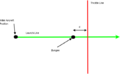
Bungee takeoff diagram
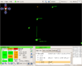
After bungee takeoff initialization
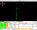
After crossing the throttle line


Polygon Survey
Explanation
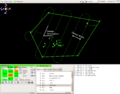
With this navigation routine, an aircraft can survey the area of any convex polygon given an entry point, the number of waypoints which define the polygon, the sweep width and the desired orientation of the sweeps.
The entry point is the first corner of the polygon and the point at which the aircraft will begin surveying the area. When in the entry state, the aircraft will circle around the entry point in order to smoothly transition into the first sweep. The aircraft will also keep circling around the entry point until it gets to the waypoint altitude. After the first sweep is made, the direction of the next sweep is determined by the distance of the entry point to the edges of the polygon. If there is more area above the first sweep, the aircraft will sweep up. If there is more area below the first sweep, the aircraft will sweep down.
The aircraft will keep sweeping back and forth until it reaches the end of the polygon. At this point, the aircraft will sweep back up/down the polygon halfway in between the sweeps previously made by the aircraft (just like the rectangle survey function). The aircraft will keep sweeping up and down the polygon unless the user manually exits the block or unless an exception is used (see below).
The orientation of the sweeps can ranges from north south to east west and any where in between (-90 <-> 90 degrees respectively). The side of the polygon the aircraft starts on (ex. north or south) is determined by the side of the polygon the entry point is located.
Sweep Definition
Entry Point
Sweeping Back


Implementation
You can add this navigation routine in your flight plan like so...
| File: conf/flight_plans/myflightplan.xml |
    <block name="Poly Survey">
      <call_once fun="nav_survey_polygon_setup(WP_S1, NumberOfCorners, AngelOfSweep, WidthOfSweep, DistanceOfASensorTrigger, MinimumTrunRadius, AltitudeOfSurvey)"/>
      <call fun="nav_survey_polygon_run()"/>
    </block>
|
The parameters are the entry waypoint, the number of waypoints in the polygon, the sweep width (meters), and the desired orientation of the sweeps (degrees). The maximum number of waypoints a polygon can have is currently ten (can be changed in the code). If the number of waypoints in the polygon exceeds the maximum number, the routine will exit and move to the next block in the flight plan. The routine will also exit if the orientation is not between -90 and 90 degrees.
Here is an example of how you should declare each of the corners of the polygon.
| File: conf/flight_plans/myflightplan.xml |
   <waypoint alt="1453.0" name="S1" x="-546.2" y="297.4"/>
   <waypoint alt="1453.0" name="S2" x="-129.8" y="744.1"/>
   <waypoint alt="1553.0" name="S3" x="1030.5" y="535.5"/>
   <waypoint alt="1453.0" name="S4" x="523.0" y="-236.7"/>
   <waypoint alt="1453.0" name="S5" x="-285.9" y="-255.7"/>
|
S1 is the entry waypoint and the first corner. The other corners should be in order clockwise or counter clockwise around the polygon. Even though this group of waypoints must be declared together, where the group appears in the list of waypoints doesn't matter.
If you want the edges of the polygon to show up on the GCS, you can also declare the polygon as a sector. This is not required to run the routine.
| File: conf/flight_plans/myflightplan.xml |
  <sectors>
    <sector name="PolySector">
      <corner name="S1"/>
      <corner name="S2"/>
      <corner name="S3"/>
      <corner name="S4"/>
      <corner name="S5"/>
    </sector>
  </sectors>
|
- A Range of Different Sweep Orientations
0 Degrees

30 Degrees
65 Degrees
90 Degrees


Alternative configurations
If you are wanting to start and stop the Poly Survey this is possible by splitting the Poly Survey code above into the initialization routine and the execution routine. You might want to do this if you are searching for something inside the Poly Survey, think you have found it and then realized you haven't, so you want to continue the survey (not restart it). Using the example above, but with the initialisation and execution code separate:
| File: conf/flight_plans/myflightplan.xml |
    <block name="Init Poly Survey">
      <call fun="InitializePolygonSurvey(WP_S1, NumOfCorners, SweepWidth, Orientation)"/>
    </block>

    <block name="Execute Poly Survey">
      <call fun="PolygonSurvey()"/>
    </block>
|
Exceptions
There are a couple of built in variables which can be used to exit the routine with an exception. PolySurveySweepNum gives the number of sweeps the aircraft has made and PolySurveySweepBackNum gives the number of times the aircraft has gotten to the bottom of the polygon and swept back. The first example would deroute the aircraft to standby after the aircraft made it's second sweep. The second example would deroute the aircraft to standby before it starts to sweep back up the polygon for the first time.
| File: conf/flight_plans/myflightplan.xml |
    <block name="Poly Survey">
       <exception cond="PolySurveySweepNum >= 2" deroute="Standby"/>
      <call fun="InitializePolygonSurvey(WP_S1, 5, 200, 45)"/>
      <call fun="PolygonSurvey()"/>
    </block>

    <block name="Poly Survey">
       <exception cond="PolySurveySweepBackNum >= 1" deroute="Standby"/>
      <call fun="InitializePolygonSurvey(WP_S1, 5, 200, 45)"/>
      <call fun="PolygonSurvey()"/>
    </block>
|
Flight Line
The Flight Line Routine allows the user to map/follow one dimensional areas of interest like roads and rivers. Given two waypoints, the routine will automatically transition into the flight line to ensure full coverage between the waypoints. In addition, distances before and after the flight line can be used to add extra security to the coverage.

To use this navigation routine, you need to include OSAMNav.h in your flight plan and OSAMNav.c to your airframe file. Then add this navigation routine in your flight plan like so...
| File: conf/flight_plans/myflightplan.xml |
    <block name="Map River">
      <call fun="FlightLine(WP_R1,WP_R2,nav_radius,distance_before,distance_after)"/>
    </block>
|
Multiple flight lines can be daisy chained by reusing waypoints as shown below...
| File: conf/flight_plans/myflightplan.xml |
    <block name="Map River">
      <call fun="FlightLine(WP_R1,WP_R2,nav_radius,100,100)"/>
      <call fun="FlightLine(WP_R2,WP_R3,nav_radius,100,100)"/>
      <call fun="FlightLine(WP_R3,WP_R4,nav_radius,100,100)"/>
      <call fun="FlightLine(WP_R5,WP_R6,nav_radius,100,100)"/>
      <deroute block="Standby"/>
    </block>
|
However, the previous block can also be implemented using the FlightLineBlock function. The FlightLineBlock function works the same as the FlightLine function except it automatically steps through the waypoints between the given waypoints. Make sure the waypoints are declared in order or else it won't work!
| File: conf/flight_plans/myflightplan.xml |
   <block name="Map River">
      <call fun="FlightLineBlock(WP_R1,WP_R6,nav_radius,100,100)"/>
      <deroute block="Standby"/>
    </block>
|
Multiple Flight Line Example

misc
Border line
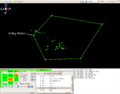
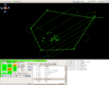
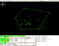
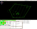
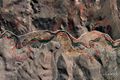
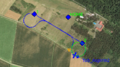
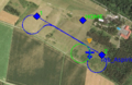
border_line is a nav-routine pretty similar to the nav-line-routine. You can use this nav-routine whenever you want to take care your plane stays on a defined site of a border. For example you can use this routine to fly along a mountain and always turn away from the mountain ridge wall. Or use it fly along a border road without penetrating the other side of the border.
Use "extra" navigation subsystem with:
<subsystem name="navigation" type="extra"/>
If you want to use waypoint 1 and 2 you can add border_line in your flight plan like this:
- Include header in "header" section at the beginning
#include "subsystems/navigation/border_line.h"
- Add function in a flight plan block:
| File: conf/flight_plans/myflightplan.xml |
    <block group="extra_pattern" name="border line">
      <call fun="border_line_init()"/>
      <call fun="border_line(WP_1, WP_2, -nav_radius)"/>
    </block>
|
- example
Screen shot of border_line
Screen shot of border_line2
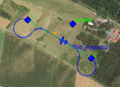
Screen shot of border_line3


GLS
GLS or Global Navigation Satellite System (GNSS) Landing System adds advanced landing functions to your flightplan
It add the following capabilities:
- Fly via defined glide path angle
- In flight changeable landing direction without loosing the glide path angle!
- Smooth intercept, independent of approach angle or wind
- Separation of approach fix, start decent and top of decent
- With fixed target speed (in airspeed mode only)
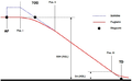
- GLS = Global Navigation Satellite System (GNSS) Landing System
- TOD = top of decent
- AF = Approach Fix
- SD = Start Decend
- TD = Touch Down point, The spot where the plane should touch the ground for landing
Configure
What to add to your airframe.
| File: conf/flight_plans/myflightplan.xml |
 <section name="GLS_APPROACH" prefix="APP_">
    <define name="ANGLE" value="5" unit="deg"/>
    <define name="INTERCEPT_RATE" value="0.624" unit="m/s/s"/>
    <define name="DISTANCE_AF_SD" value="20" unit="m"/>
    <define name="TARGET_SPEED" value="14" unit="m/s"/>
  </section>
|
ANGLE - angle from TOD to TD
DISTANCE_AF_SD - minimum distance (meter) between AF and SD to allow the plane to self stabilize before the intercept starts (e.g. for speed reduction)
You can set the landing direction by moving the approach fix (AF) in relation to the touch down point (TD). If you try to set the AF close to the TD you will see how the top of decent (TOD) and start decent (SD) is calculated and if necessary the AF is moved backwards. (please try in simulation)
TARGET_SPEED - desired airspeed from AF to TD
INTERCEPT_RATE -
e.g. no wind: TARGET_SPEED = 14m/s and ANGLE = 10 --> desired decent rate 2.5 m/s (speed * tan(ANGLE))
with an INTERCEPT_RATE of 0.624 m/s/s it will take 4s to intercept the final approach path (desired decent rate / intercept_rate)
the idea is that the INTERCEPT_RATE is unique to each plane and will not change with different approach angles
to find an appropriate value you can start with a lower (to match 8s for example) and increase it until the intercept will be made from above
in general: bigger plane - smaller value!
how to setup your flightplan.xml:
  <waypoints>
    <waypoint height="150" name="AF" x="-260.6" y="-344.6"/>
    <waypoint name="SD" x="-1600." y="-36."/>
    <waypoint name="TOD" x="-1600." y="-36."/>
    <waypoint height="0.0" name="TD" x="-27.2" y="-243.5"/>
    <waypoint height="266.0" name="_BASELEG" x="-1652.1" y="-113.5"/>
  </waypoints>


    <block name="land">
      <call fun="gls_init(WP_AF,WP_SD, WP_TOD, WP_TD)"/>
      <call fun="nav_compute_baseleg(WP_AF, WP_TD, WP__BASELEG, nav_radius)"/>
      <circle radius="nav_radius" until="NavCircleCount() > 0.5" wp="_BASELEG"/>
      <circle radius="nav_radius" until="And(NavQdrCloseTo(DegOfRad(baseleg_out_qdr)-(nav_radius/fabs(nav_radius))*10),
                               10 > fabs(GetPosAlt() - WaypointAlt(WP__BASELEG)))" wp="_BASELEG"/>
    </block>

    <block name="final">
      <exception cond="ground_alt + 10 > estimator_z" deroute="flare"/>
      <call fun="gls(WP_AF,WP_SD, WP_TOD, WP_TD)"/>
    </block>
those pictures match the old gls routine! anyway - the new one is not much different... (POS I = SD)
- theory
side view
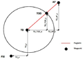
from above
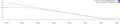
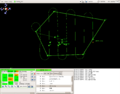
screen shot of flight test


Multi-UAV
For TCAS (Traffic Collision Avoidance System) see the MultiUAV page.
Creating a navigation module is not to complex. Have said that, it is not very likely to need to create one module oneself. The already available functions are very flexible and powerful. Before you set of to create and additional navigation module, make sure you understand all current modules and their capabilities. After you investigated current modules and came to the conclusion, there is no way to solve you flightplan mission by creating a new module, go ahead and plz share your work with the community. The more people test the new module, the faster it will reach a stable state.