Difference between revisions of "Umarim v1.0"
Jump to navigation
Jump to search
(→Pinout) |
(→Pinout) |
||
| Line 28: | Line 28: | ||
[[Image:Umarim_v1-0_pinout.png]] | [[Image:Umarim_v1-0_pinout.png]] | ||
{|border="1" cellspacing="0" style="text-align:center" cellpadding="6" | |||
|+'''SRV0/1/2/3/6/7''' | |||
!''Pin #''!!width="80"|''Name''!!''Type''!!width="500"|''Description''!!width="50"|''Suggested Color'' | |||
|- | |||
|1||GND||PWR||common ground||style="background:black; color:white"|Black | |||
|- | |||
|2|| +5V||PWR||5V Rail from autopilot||style="background:Orange; color:white"|Orange | |||
|- | |||
|3||SRVx||OUT||Servo signal (PWM)||White | |||
|} | |||
{|border="1" cellspacing="0" style="text-align:center" cellpadding="6" | |||
|+'''RC''' | |||
!''Pin #''!!width="80"|''Name''!!''Type''!!width="500"|''Description''!!width="50"|''Suggested Color'' | |||
|- | |||
|1||GND||PWR||common ground||style="background:black; color:white"|Black | |||
|- | |||
|2|| +5v||PWR||5V Rail from autopilot||style="background:Orange; color:white"|Orange | |||
|- | |||
|3||PPM_IN||IN||PPM Stream from R/C Receiver (5V tolerant)||style="background:white; color:black"|White | |||
|} | |||
{|border="1" cellspacing="0" style="text-align:center" cellpadding="6" | |||
|+'''SPI1''' | |||
!''Pin #''!!width="80"|''Name''!!''Type''!!width="500"|''Description''!!width="50"|''Suggested Color'' | |||
|- | |||
|1||GND||PWR||common ground||style="background:black; color:white"|Black | |||
|- | |||
|2|| +3.3V||PWR||3.3V Rail from autopilot||style="background:red; color:white"|Red | |||
|- | |||
|3||SSEL1||IN||SSP Slave Select. Selects the SSP interface as a slave (SSEL1)||style="background:sienna; color:white"|Brown | |||
|- | |||
|4||MOSI1||I/O||SPI1 Master Out Slave In. Data output from master / data input to slave||style="background:Grey; color:white"|Grey | |||
|- | |||
|5||MISO1||I/O||SPI1 Master In Slave Out. Data input to master / data output from slave||style="background:Green; color:white"|Green | |||
|- | |||
|6||DRDY1||IN||External interrupt 0 input (EINT0)||style="background:Purple; color:white"|Purple | |||
|- | |||
|7||SCK1||I/O||SPI1 Serial clock. Clock output from master or input to slave||style="background:Yellow; color:black"|Yellow | |||
|} | |||
{|border="1" cellspacing="0" style="text-align:center" cellpadding="6" | |||
|+'''AUX''' | |||
!''Pin #''!!width="80"|''Name''!!''Type''!!width="500"|''Description''!!width="50"|''Suggested Color'' | |||
|- | |||
|1||GND||PWR||common ground||style="background:black; color:white"|Black | |||
|- | |||
|2|| +5V||PWR||5V Rail from autopilot||style="background:Orange; color:white"|Orange | |||
|- | |||
|3|| +3.3V||PWR||3.3V Rail from autopilot||style="background:Red; color:white"|Red | |||
|- | |||
|4||AUX1||I/O||General Purpose I/O #1 or ADC input (AD1.5)|| | |||
|- | |||
|5||AUX2||I/O||General Purpose I/O #2 or ADC input (AD1.4)|| | |||
|- | |||
|6||AUX3||I/O||General Purpose I/O #3 or ADC input (AD1.3)|| | |||
|- | |||
|7||AUX4||I/O||General Purpose I/o #4 or ADC input (AD1.2)|| | |||
|} | |||
{|border="1" cellspacing="0" style="text-align:center" cellpadding="6" | {|border="1" cellspacing="0" style="text-align:center" cellpadding="6" | ||
| Line 58: | Line 122: | ||
{|border="1" cellspacing="0" style="text-align:center" cellpadding="6" | {|border="1" cellspacing="0" style="text-align:center" cellpadding="6" | ||
|+''' | |+'''I2C0''' | ||
!''Pin #''!!width="80"|''Name''!!''Type''!!width="500"|''Description''!!width="50"|''Suggested Color'' | !''Pin #''!!width="80"|''Name''!!''Type''!!width="500"|''Description''!!width="50"|''Suggested Color'' | ||
|- | |- | ||
|1||GND||PWR||common ground||style="background:black; color:white"|Black | |1||GND||PWR||common ground||style="background:black; color:white"|Black | ||
|- | |- | ||
|2|| | |2|| +3.3V||PWR||3.3V Rail from autopilot||style="background:red; color:white"|Red | ||
|- | |- | ||
|3|| | |3||SDA0||I/O (Open Drain)||I2C0 bus Serial DAta||style="background:sienna; color:white"|Brown | ||
|- | |- | ||
|4|| | |4||SCL0||I/O (Open Drain)||I2C0 bus Serial CLock||style="background:blue; color:white"|Blue | ||
|} | |} | ||
{|border="1" cellspacing="0" style="text-align:center" cellpadding="6" | {|border="1" cellspacing="0" style="text-align:center" cellpadding="6" | ||
|+''' | |+'''I2C1''' | ||
!''Pin #''!!width="80"|''Name''!!''Type''!!width="500"|''Description''!!width="50"|''Suggested Color'' | !''Pin #''!!width="80"|''Name''!!''Type''!!width="500"|''Description''!!width="50"|''Suggested Color'' | ||
|- | |- | ||
| Line 79: | Line 143: | ||
|2|| +3.3V||PWR||3.3V Rail from autopilot||style="background:red; color:white"|Red | |2|| +3.3V||PWR||3.3V Rail from autopilot||style="background:red; color:white"|Red | ||
|- | |- | ||
|3|| | |3||SDA1<br>BOOT||I/O (Open Drain)||I2C1 bus Serial DAta<br>In-Circuit Serial Programming (ISP) enable (P0.14, +3.3v pullup) ''(Note)''||style="background:sienna; color:white"|Brown | ||
|- | |||
|4||SCL1||I/O (Open Drain)||I2C1 bus Serial CLock||style="background:blue; color:white"|Blue | |||
|} | |||
''Note: Holding this pin low for at least 3mS after a RESET (or power up) instructs the controller to enter programming mode.'' | |||
{|border="1" cellspacing="0" style="text-align:center" cellpadding="6" | |||
|+'''USB''' | |||
!''Pin #''!!width="80"|''Name''!!''Type''!!width="500"|''Description''!!width="50"|''Suggested Color'' | |||
|- | |- | ||
| | |1||GND||PWR||common ground||style="background:black; color:white"|Black | ||
|- | |- | ||
| | |2||USB+||I/O||USB bidirectional D+ line||style="background:green; color:white"|Green | ||
|- | |- | ||
| | |3||USB-||I/O||USB bidirectional D- line||style="background:white; color:black"|White | ||
|- | |- | ||
| | |4||VBUS||IN||Indicates the presence of USB bus power (P0.23) (5V level)||style="background:orange; color:white"|Orange | ||
|} | |} | ||
Revision as of 10:29, 23 September 2011
...UNDER CONSTRUCTION...

Hardware Revision History
| Version # | Release Date | Release Notes |
|---|---|---|
| v1.0 | 09/2011 | Initial release of Umarim |
Features
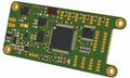
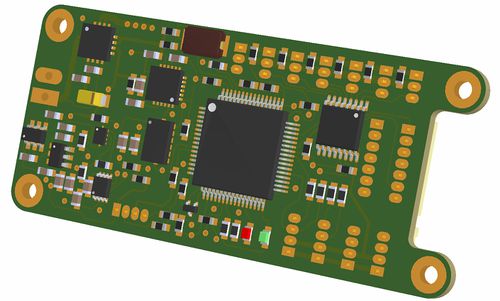
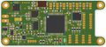
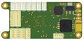
Umarim v1.0 3D bottom view
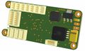
Umarim v1.0 3D top view

Architecture
Pinout
Pins Name and Type are specified with respect to the Autopilot Board

| Pin # | Name | Type | Description | Suggested Color |
|---|---|---|---|---|
| 1 | GND | PWR | common ground | Black |
| 2 | +5V | PWR | 5V Rail from autopilot | Orange |
| 3 | SRVx | OUT | Servo signal (PWM) | White |
| Pin # | Name | Type | Description | Suggested Color |
|---|---|---|---|---|
| 1 | GND | PWR | common ground | Black |
| 2 | +5v | PWR | 5V Rail from autopilot | Orange |
| 3 | PPM_IN | IN | PPM Stream from R/C Receiver (5V tolerant) | White |
| Pin # | Name | Type | Description | Suggested Color |
|---|---|---|---|---|
| 1 | GND | PWR | common ground | Black |
| 2 | +3.3V | PWR | 3.3V Rail from autopilot | Red |
| 3 | SSEL1 | IN | SSP Slave Select. Selects the SSP interface as a slave (SSEL1) | Brown |
| 4 | MOSI1 | I/O | SPI1 Master Out Slave In. Data output from master / data input to slave | Grey |
| 5 | MISO1 | I/O | SPI1 Master In Slave Out. Data input to master / data output from slave | Green |
| 6 | DRDY1 | IN | External interrupt 0 input (EINT0) | Purple |
| 7 | SCK1 | I/O | SPI1 Serial clock. Clock output from master or input to slave | Yellow |
| Pin # | Name | Type | Description | Suggested Color |
|---|---|---|---|---|
| 1 | GND | PWR | common ground | Black |
| 2 | +5V | PWR | 5V Rail from autopilot | Orange |
| 3 | +3.3V | PWR | 3.3V Rail from autopilot | Red |
| 4 | AUX1 | I/O | General Purpose I/O #1 or ADC input (AD1.5) | |
| 5 | AUX2 | I/O | General Purpose I/O #2 or ADC input (AD1.4) | |
| 6 | AUX3 | I/O | General Purpose I/O #3 or ADC input (AD1.3) | |
| 7 | AUX4 | I/O | General Purpose I/o #4 or ADC input (AD1.2) |
| Pin # | Name | Type | Description | Suggested Color |
|---|---|---|---|---|
| 1 | GND | PWR | common ground | Black |
| 2 | +3.3V | PWR | 3.3V Rail from autopilot | Red |
| 3 | RXD0 | IN | UART0 Serial Input (3.3V level, 5V Tolerant) | Green |
| 4 | TXD0 | OUT | UART0 Serial Output (3.3V level) | Blue |
| Pin # | Name | Type | Description | Suggested Color |
|---|---|---|---|---|
| 1 | GND | PWR | common ground | Black |
| 2 | +3.3V | PWR | 3.3V Rail from autopilot | Red |
| 3 | RXD1 | IN | UART1 Serial Input (3.3V level, 5V Tolerant) | Green |
| 4 | TXD1 | OUT | UART1 Serial Output (3.3V level) | Blue |
| Pin # | Name | Type | Description | Suggested Color |
|---|---|---|---|---|
| 1 | GND | PWR | common ground | Black |
| 2 | +3.3V | PWR | 3.3V Rail from autopilot | Red |
| 3 | SDA0 | I/O (Open Drain) | I2C0 bus Serial DAta | Brown |
| 4 | SCL0 | I/O (Open Drain) | I2C0 bus Serial CLock | Blue |
| Pin # | Name | Type | Description | Suggested Color |
|---|---|---|---|---|
| 1 | GND | PWR | common ground | Black |
| 2 | +3.3V | PWR | 3.3V Rail from autopilot | Red |
| 3 | SDA1 BOOT |
I/O (Open Drain) | I2C1 bus Serial DAta In-Circuit Serial Programming (ISP) enable (P0.14, +3.3v pullup) (Note) |
Brown |
| 4 | SCL1 | I/O (Open Drain) | I2C1 bus Serial CLock | Blue |
Note: Holding this pin low for at least 3mS after a RESET (or power up) instructs the controller to enter programming mode.
| Pin # | Name | Type | Description | Suggested Color |
|---|---|---|---|---|
| 1 | GND | PWR | common ground | Black |
| 2 | USB+ | I/O | USB bidirectional D+ line | Green |
| 3 | USB- | I/O | USB bidirectional D- line | White |
| 4 | VBUS | IN | Indicates the presence of USB bus power (P0.23) (5V level) | Orange |
Schematic
PCB
Gerber & Drill Files
Assembly
Umarim v1.0 bottom components Layout
Umarim v1.0 top components Layout

