MeekPE PPM Encoder Board
(PRELIMINARY)
MeekPE is a MCUless PPM Encoder.
This small board encode the PPM signal from the R/C receiver servo outputs without using any microcontroller.
Any type of R/C receiver is directly usable without any hardware modification.

Hardware Revision History
| Version # | Release Date | Release Notes |
|---|---|---|
| v1.00 | in progress... | 0603/TSSOP PCB design |
| v0.10 (current) | 08/2007 | 0805/SOIC Single layer test PCB design |
| v0.00 | 07/2010 | Ugly Prototype |
Features
- no MCU => no software
- up to 8 servo encoding inputs
- 25.4 x 15.6mm (1.0 x 0.6")
- ..g (..oz)
Block Diagram
Prototypes
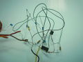
First ugly test (this is note a joke)
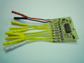
Test board 0805/SOIC components


Pinout

| Pin # | Name | Type | Description | Suggested Color |
|---|---|---|---|---|
| 1 | GND | PWR | Common ground | Black |
| 2 | +5V | PWR | 5V to R/C receiver supply (optional, see connection instructions below) | Red or Orange |
| 3 to 9 | SERVO | IN | From R/C receiver servo output (see connection instructions below) | Yellow |
| 10 | LAST SERVO | IN | From R/C receiver servo output. Last channel to be encoded (see connection instructions below) | White |
| Pin # | Name | Type | Description | Suggested Color |
|---|---|---|---|---|
| 1 | GND | PWR | Common ground | Black |
| 2 | +5V | PWR | 5V rail from autopilot (see connection instructions below) | Red or Orange |
| 3 | PPM | OUT | Positive logic PPM output | Blue |
Connections
MeekPE to Autopilot
Ground, Power ("+5V") and PPM signal must be connected to the autopilot.
Power ("+5V") pin is used to supply the MeekPE board (+3.5V to +16V) and can also supply your receiver. In this case, MeekPE supply voltage must match your R/C receiver power supply voltage (around +5V in general).
You can use a classic Molex 3 pin connector or solder wires directly on board: 3 additional bigger thru-hole pads are provided for this purpose.
R/C receiver to MeekPE
You can use a classic 0.1" pitch break away header and female/female jumper wires (like SparkFun's PRT-08430) or cut in half SparkFun's PRT-08430 female/female jumper wires and solder it directly to the MeekPe.
Powering the R/C receiver
- Ground connection is mandatory (voltage reference between the R/C receiver and the MeekPE encoder)
- Power output pin ("+5V") is used only if you decide to supply your receiver with the autopilot. In this case, MeekPE supply voltage from the A/P must match your R/C receiver power supply voltage (around +5V in general)
Servo connections rules
To get a correct PPM encoded signal, you must follow some (simple) rules:
- You must know the channel number of the first and the last servo signal you want to encode.
- All servo connection between the first and last channel you want to encode must be connected, even if you don't use it in the autopilot code.
- The last channel number servo signal you want to encode must be connected to the "LAST-SERVO" input pin of the MeekPE encoder. Other servos connections can be in any order because the channel encoding number is given by the transmitter, not by the MeekPE encoder.
Servo connection example
Ok, finally, servo connection rules are not so simple. So perhaps will it be better understandable with some examples.
- 6 channel receiver, you want to encode Throttle (channel#1), Pitch (channel#2), Roll (channel#3), and Mode Switch (channel#5):
=> connect #1, 2, 3, 4 R/C receiver servo output to any MeekPE servo input and servo R/C receiver servo output #5 on "LAST SERVO" MeekPE input. You can leave #6 unconnected.
- 8 channel receiver, you want to encode channel#2 to channel#5 and channel#7:
=> connect #2, 3, 4, 5, 6 R/C receiver servo output to any MeekPE servo input and servo R/C receiver servo output #7 on "LAST SERVO" MeekPE input. You can leave #8 unconnected.
Schematic

PCB
Gerber & Drill Files
Assembly
Components Layout
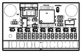
MeekPE v1.00 Components Layout
