Difference between revisions of "MeekPE PPM Encoder Board"
| Line 65: | Line 65: | ||
=== MeekPE to Autopilot === | === MeekPE to Autopilot === | ||
Ground, Power ("+5V") and PPM signal must be connected to the autopilot.<br> | Ground, Power ("+5V") and PPM signal must be connected to the autopilot.<br> | ||
Power ("+5V") pin is used to supply the MeekPE board (+3.5V to +16V) and can also supply your receiver. In this case, MeekPE supply voltage must match your R/C receiver power supply voltage (around +5V in general) | Power ("+5V") pin is used to supply the MeekPE board (+3.5V to +16V) and can also supply your receiver. In this case, MeekPE supply voltage must match your R/C receiver power supply voltage (around +5V in general).<br> | ||
You can use a classic Molex 3 pin connector or solder wires directly on board: 3 additional bigger thru-hole pads are provided for this purpose.<br> | You can use a classic Molex 3 pin connector or solder wires directly on board: 3 additional bigger thru-hole pads are provided for this purpose.<br> | ||
=== R/C receiver to MeekPE === | === R/C receiver to MeekPE === | ||
You can: | You can: | ||
Revision as of 02:18, 20 August 2010
(PRELIMINARY)
MeekPE is a MCUless PPM Encoder.
This small board encode the PPM signal from the R/C receiver servo outputs without using any microcontroller.
Any type of R/C receiver is directly usable without any hardware modification.

Hardware Revision History
| Version # | Release Date | Release Notes |
|---|---|---|
| v1.00 | in progress... | 0603/TSSOP PCB design |
| v0.10 (current) | 08/2007 | 0805/SOIC Single layer test PCB design |
| v0.00 | 07/2010 | Ugly Prototype |
Features
- no MCU => no software
- up to 8 servo encoding inputs
- 25.4 x 15.6mm (1.0 x 0.6")
- ..g (..oz)
Architecture
Prototypes
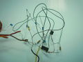
First ugly test (this is note a joke)
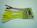
Test board 0805/SOIC components


Pinout

| Pin # | Name | Type | Description | Suggested Color |
|---|---|---|---|---|
| 1 | GND | PWR | Common ground | Black |
| 2 | +5V | PWR | 5V to R/C receiver supply (optional) | Red or Orange |
| 3 to 9 | SERVO | IN | From R/C receiver servo output (see connection instructions below) | Yellow |
| 10 | LAST SERVO | IN | From R/C receiver servo output. Last channel to be encoded | White |
| Pin # | Name | Type | Description | Suggested Color |
|---|---|---|---|---|
| 1 | GND | PWR | Common ground | Black |
| 2 | +5V | PWR | 5V rail from autopilot (see connection instructions below) | Red or Orange |
| 3 | PPM | OUT | PPM output | Blue |
Connections
MeekPE to Autopilot
Ground, Power ("+5V") and PPM signal must be connected to the autopilot.
Power ("+5V") pin is used to supply the MeekPE board (+3.5V to +16V) and can also supply your receiver. In this case, MeekPE supply voltage must match your R/C receiver power supply voltage (around +5V in general).
You can use a classic Molex 3 pin connector or solder wires directly on board: 3 additional bigger thru-hole pads are provided for this purpose.
R/C receiver to MeekPE
You can:
- use a classic 0.1" pitch break away header and female/female jumper wires (like SparkFun's PRT-08430)
- cut in half SparkFun's PRT-08430 female/female jumper wires and solder it directly to the MeekPe.
Powering the R/C receiver
- Ground connection is mandatory (voltage reference between the R/C receiver and the MeekPE encoder)
- Power ("+5V") pin is used only if you decide to supply your receiver with the autopilot. In this case, MeekPE supply voltage must match your R/C receiver power supply voltage (around +5V in general)
Servo connections rules
To get a correct PPM encoded signal, you must follow some (simple) rules:
Servo connection example
Schematic
