File:Tiny test wiring.jpg
Original file (1,707 × 1,353 pixels, file size: 325 KB, MIME type: image/jpeg)
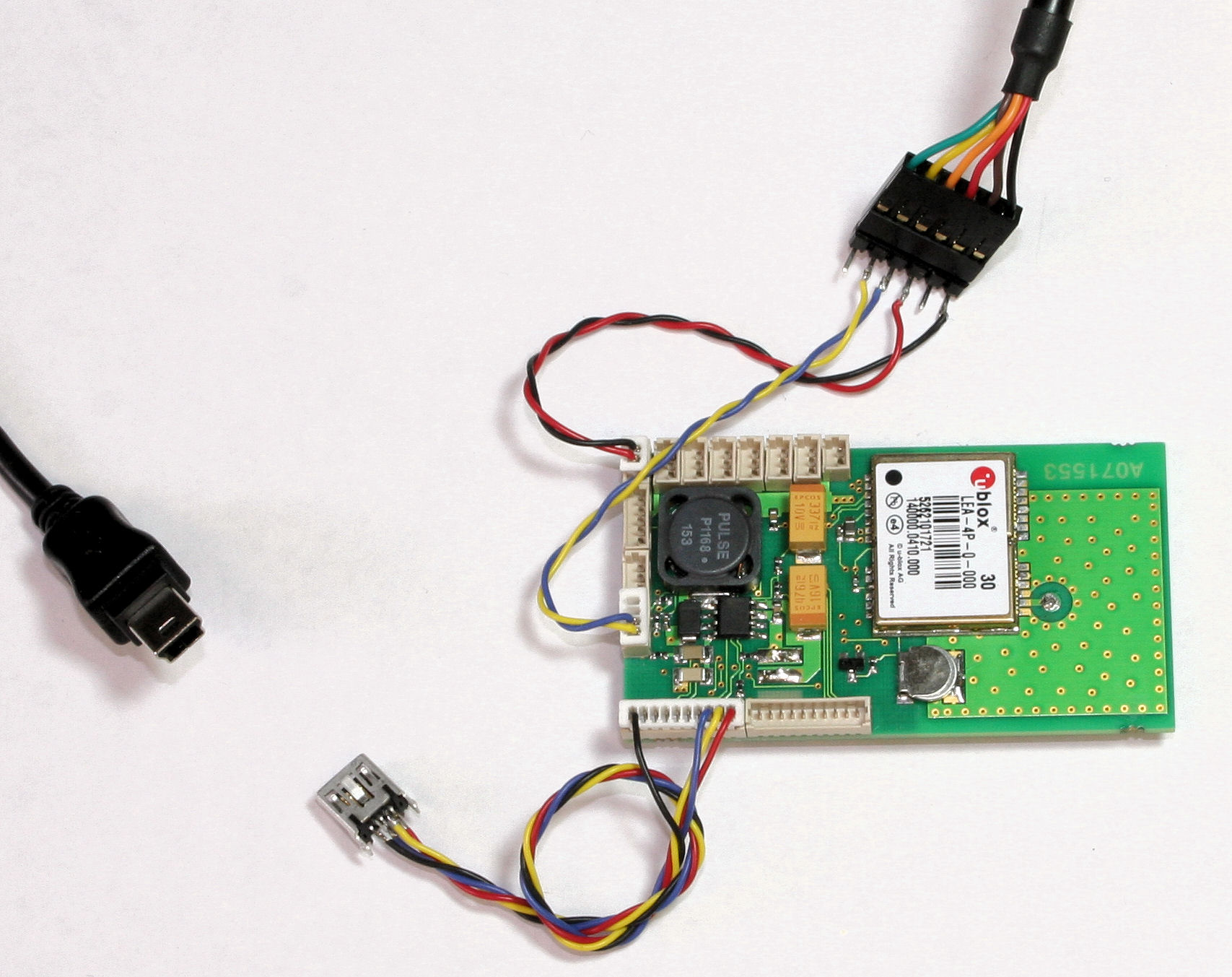
Basic minimum wiring for programming and testing. FTDI TTL-232R cable at the top right provides serial flashing of the bootloader or serial telemetry data to the ground station. Note the 5V USB power from the FTDI can be connected to the servo bus to power the autopilot if you are as lazy as I am and don't want to connect proper 6-16V power to the regulator input. Normal users should connect only 3 wires (ground, TX, RX) not this +5V wire!
USB flashing is performed thru the mini-B receptacle (Mouser P/N 500075-0517) Top row wiring left to right: open, yellow Bottom row: black, blue, red
File history
Click on a date/time to view the file as it appeared at that time.
| Date/Time | Thumbnail | Dimensions | User | Comment | |
|---|---|---|---|---|---|
| current | 04:19, 8 January 2014 | | 1,707 × 1,353 (325 KB) | Maintenance script (talk) | Importing file |
| 16:56, 22 February 2007 | No thumbnail | 1,707 × 1,353 (325 KB) | Jeremy (talk | contribs) | Basic minimum wiring for programming and testing. FTDI TTL-232R cable at the top right provides serial flashing of the bootloader or serial telemetry data to the ground station. Note the 5V USB power from the FTDI can be connected to the servo bus to po |
You cannot overwrite this file.
File usage
The following page uses this file: