Difference between revisions of "Lpc21BootloaderUpload"
m |
|||
| Line 1: | Line 1: | ||
== | ==Bootloader from scatch== | ||
The | The goal of this page is to explain how to get the autopilot bootloader onto a ''brainless'' new ARM based autopilot board. Note that the bootloader only needs to be installed '''once''', when the board is first built and has never been used. Most of the times if you bought a board somewhere, the bootloader is already installed for you. If you did not make and soldered the Autopilot board yourself but bought it somewhere, chances are high the bootloader is already uploaded onto your board by the manufacturer. You could ask the supplier of your board. In that case you can just '''skip''' the steps described here and just continue the part of [http://paparazzi.enac.fr/wiki/Paparazzi_Center Uploading the Flightplan code to your autopilot board] or if you are more experienced you could go [http://paparazzi.enac.fr/wiki/Compiling here] | ||
[Image:Bare_TWOG_Board.jpg|thumb|right|Bare_TWOG_Board.jpg] | |||
==Why have Bootloader in the first place== | |||
Since the Airborne code and Flight-plans change frequently, it would be great if we could just simply upload new version with changes on the ground by connecting an USB cable to out airframes autopilot board. Well, the Bootloader makes this a simple reality. | |||
==How does it work== | |||
The Bootloader is uploaded through the serial interface UART0 (Serial1) by connecting certain point on the board to '''ground''' during power-up, sometimes referred to as: ''holding low''. On the board Tiny V1.x pin P0.14, Tiny V2.x this pin is called BOOT). Also GPS_RESET has to be tied low during the serial programming to keep the GPS receiver quiet that shares the serial port with the download. | |||
==Connecting it all== | |||
You will need to convert the PC's RS232 Serial with voltage levels of +/-13V to 3.3V (or 5V) TTL in order to communicate directly with the Autopilot board. This can be accomplished in multiple ways. The easiest and most convenient method is to purchase or build a USB -> Serial 3.3V adapter similar to this one [http://www.ftdichip.com/Products/EvaluationKits/TTL-232R-3V3.htm TTL-232R-3V3] [[Image:The_FTDI_RS232_USB_Cable.jpg|thumb|right|The FTDI RS232 USB Cable]] | You will need to convert the PC's RS232 Serial with voltage levels of +/-13V to 3.3V (or 5V) TTL in order to communicate directly with the Autopilot board. This can be accomplished in multiple ways. The easiest and most convenient method is to purchase or build a USB -> Serial 3.3V adapter similar to this one [http://www.ftdichip.com/Products/EvaluationKits/TTL-232R-3V3.htm TTL-232R-3V3] [[Image:The_FTDI_RS232_USB_Cable.jpg|thumb|right|The FTDI RS232 USB Cable]] | ||
| Line 11: | Line 23: | ||
[http://www.hvwtech.com/products_view.asp?CatID=166&SubCatID=183&SubSubCatID=0&ProductID=409] | [http://www.hvwtech.com/products_view.asp?CatID=166&SubCatID=183&SubSubCatID=0&ProductID=409] | ||
It is strongly advised that you use a USB-serial converter with of the [www.ftdichip.com/ FTDI brand] chip as | It is strongly advised that you use a USB-serial converter with of the [www.ftdichip.com/ FTDI brand] chip, as serial chips from the FTDI brand are by default working well in Linux. As a nice bonus, the Paparazzi ground station software is configured to look for modems on FTDI ports by default, the converter can likely serve as a modem interface after it's use in Bootloader uploading. | ||
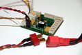
Make up a wiring harness similar to the following. | Make up a wiring harness similar to the following. | ||
| Line 30: | Line 42: | ||
TINY RESET --> ''optional'' wired to ground through a pushbutton so you can reset | TINY RESET --> ''optional'' wired to ground through a pushbutton so you can reset | ||
Tiny V2.x (Connectorname - DOWNLOAD) :<br /> | |||
Tiny V2.x (DOWNLOAD):<br /> | |||
TINY LPC_RXD0 <-- PC SERIAL TX (5V or 3.3V) | TINY LPC_RXD0 <-- PC SERIAL TX (5V or 3.3V) | ||
TINY LPC_TXD0 --> PC SERIAL RX (5V or 3.3V) | TINY LPC_TXD0 --> PC SERIAL RX (5V or 3.3V) | ||
| Line 38: | Line 49: | ||
TINY GND --> PC SERIAL ADAPTER GND | TINY GND --> PC SERIAL ADAPTER GND | ||
TWOG V1.x (Connectorname - DOWNLOAD):<br /> | |||
TWOG V1.x (DOWNLOAD):<br /> | |||
TWOG LPC_RXD0 <-- PC SERIAL TX (5V or 3.3V) | TWOG LPC_RXD0 <-- PC SERIAL TX (5V or 3.3V) | ||
TWOG LPC_TXD0 --> PC SERIAL RX (5V or 3.3V) | TWOG LPC_TXD0 --> PC SERIAL RX (5V or 3.3V) | ||
| Line 47: | Line 57: | ||
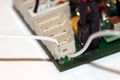
For TWOG make sure the GPS module is '''unplugged''' from the board. This is to prevent GPS serial data to disturb the uploading of the bootloader. | For TWOG make sure the GPS module is '''unplugged''' from the board. This is to prevent GPS serial data to disturb the uploading of the bootloader. | ||
[[Image:Where_To_Insert_Bootloader_Cable.jpg|thumb|right|Where to insert Bootloader cable]] | [[Image:Where_To_Insert_Bootloader_Cable.jpg|thumb|right|Where to insert the Bootloader cable]] | ||
==Upload the firmware== | |||
Once this wiring is ready you will be ready to upload the | Once this wiring is ready you will be ready to upload the bootloader to the autopilot board from your PC. | ||
To prepare the Autopilot board to accept uploads over it's serial port you must have pin P0.14 LOW for at least 3ms while it is powering up or resetting. While it is still powered up it is ready to accept the Bootloader firmware code upload over the serial connection. | To prepare the Autopilot board to accept uploads over it's serial port you must have pin P0.14 LOW for at least 3ms while it is powering up or resetting. While it is still powered up it is ready to accept the Bootloader firmware code upload over the serial connection. | ||
| Line 62: | Line 74: | ||
<gallery> | <gallery> | ||
Image:TWOG_Bootloader_Overview.jpg|TWOG Bootloader overview | Image:TWOG_Bootloader_Overview.jpg|TWOG Bootloader overview | ||
Image:Powerup_Now.jpg|Everything ready to be powered-up now | |||
</gallery> | </gallery> | ||
| Line 74: | Line 86: | ||
This will begin compiling your USB Bootloader and then attempt to transfer it to the Autopilot board. This will also assume you are using a USB -> Serial adapter for the connection. It uses /dev/ttyUSB0 by default. If your adapter is mapped to a different tty, you will need to modify the Makefile accordingly. | This will begin compiling your USB Bootloader and then attempt to transfer it to the Autopilot board. This will also assume you are using a USB -> Serial adapter for the connection. It uses /dev/ttyUSB0 by default. If your adapter is mapped to a different tty, you will need to modify the Makefile accordingly. | ||
[[Image:Shell_bootloader_upload_success.jpg|thumb|Shell Bootloader upload success]] | [[Image:Wait_For_Bootloader_To_Upload.jpg|thumb|left|Wait for the bootloader to upload]] | ||
If everything is connected and setup correctly, after a while you will see the following messages | |||
[[Image:Shell_bootloader_upload_success.jpg|thumb|left|Shell Bootloader upload success]] | |||
'''In Windows''' | '''In Windows''' | ||
| Line 84: | Line 103: | ||
If for some reason you need to program your autopilot board USB Bootloader in MS Windows you have to download the [http://www.standardics.nxp.com/support/documents/microcontrollers/zip/flash.isp.utility.lpc2000.zip LPC2000 Flash Utility V2.2.3] or later. You will then prepare the autopilot board and start it in ISP bootloader state as described in the previous. This small utility will ony help uploading the Bootloder firmware. You will need to copy your compiled '''bl.hex''' file from Linux to your Windows OS. This file will be then uploaded. | If for some reason you need to program your autopilot board USB Bootloader in MS Windows you have to download the [http://www.standardics.nxp.com/support/documents/microcontrollers/zip/flash.isp.utility.lpc2000.zip LPC2000 Flash Utility V2.2.3] or later. You will then prepare the autopilot board and start it in ISP bootloader state as described in the previous. This small utility will ony help uploading the Bootloder firmware. You will need to copy your compiled '''bl.hex''' file from Linux to your Windows OS. This file will be then uploaded. | ||
==Additional information== | |||
In depth info about the | In depth info about the bootloader can be found on the [http://paparazzi.enac.fr/wiki/Reference/bootloader Bootloader reference] page. Also the [http://paparazzi.enac.fr/wiki/DevGuide/USBDownload page here explains some more]] | ||
http://paparazzi.enac.fr/wiki/DevGuide/USBDownload | |||
Revision as of 05:32, 27 June 2010
Bootloader from scatch
The goal of this page is to explain how to get the autopilot bootloader onto a brainless new ARM based autopilot board. Note that the bootloader only needs to be installed once, when the board is first built and has never been used. Most of the times if you bought a board somewhere, the bootloader is already installed for you. If you did not make and soldered the Autopilot board yourself but bought it somewhere, chances are high the bootloader is already uploaded onto your board by the manufacturer. You could ask the supplier of your board. In that case you can just skip the steps described here and just continue the part of Uploading the Flightplan code to your autopilot board or if you are more experienced you could go here
[Image:Bare_TWOG_Board.jpg|thumb|right|Bare_TWOG_Board.jpg]
Why have Bootloader in the first place
Since the Airborne code and Flight-plans change frequently, it would be great if we could just simply upload new version with changes on the ground by connecting an USB cable to out airframes autopilot board. Well, the Bootloader makes this a simple reality.
How does it work
The Bootloader is uploaded through the serial interface UART0 (Serial1) by connecting certain point on the board to ground during power-up, sometimes referred to as: holding low. On the board Tiny V1.x pin P0.14, Tiny V2.x this pin is called BOOT). Also GPS_RESET has to be tied low during the serial programming to keep the GPS receiver quiet that shares the serial port with the download.
Connecting it all
You will need to convert the PC's RS232 Serial with voltage levels of +/-13V to 3.3V (or 5V) TTL in order to communicate directly with the Autopilot board. This can be accomplished in multiple ways. The easiest and most convenient method is to purchase or build a USB -> Serial 3.3V adapter similar to this one TTL-232R-3V3

Some examples of suppliers: [1] [2] [3] [4]
It is strongly advised that you use a USB-serial converter with of the [www.ftdichip.com/ FTDI brand] chip, as serial chips from the FTDI brand are by default working well in Linux. As a nice bonus, the Paparazzi ground station software is configured to look for modems on FTDI ports by default, the converter can likely serve as a modem interface after it's use in Bootloader uploading.
Make up a wiring harness similar to the following.

Bootloader cable
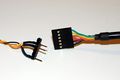
Bootloader cable to FTDI USB
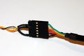
Bootloader helper cable to USB FTDI cable


You may vary the details, however this is a working solution:
Tiny V1.x (SERIAL_1):

TINY RXD0  <-- PC SERIAL TX (5V or 3.3V)
TINY TXD0  --> PC SERIAL RX (5V or 3.3V)
TINY P0.14 --> attach to ground, or wire through a pushbutton to ground
TINY GND   --> PC SERIAL ADAPTER GND
TINY RESET --> optional wired to ground through a pushbutton so you can reset
Tiny V2.x (Connectorname - DOWNLOAD) :

TINY LPC_RXD0  <-- PC SERIAL TX (5V or 3.3V)
TINY LPC_TXD0  --> PC SERIAL RX (5V or 3.3V)
TINY BOOT      --> attach to ground, or wire through a pushbutton to ground
TINY GPS_RESET --> attach to ground, or wire through a pushbutton to ground
TINY GND       --> PC SERIAL ADAPTER GND
TWOG V1.x (Connectorname - DOWNLOAD):

TWOG LPC_RXD0  <-- PC SERIAL TX (5V or 3.3V)
TWOG LPC_TXD0  --> PC SERIAL RX (5V or 3.3V)
TWOG BOOT      --> attach to ground, or wire through a pushbutton to ground
TWOG GND       --> PC SERIAL ADAPTER GND
For TWOG make sure the GPS module is unplugged from the board. This is to prevent GPS serial data to disturb the uploading of the bootloader.

Upload the firmware
Once this wiring is ready you will be ready to upload the bootloader to the autopilot board from your PC.
To prepare the Autopilot board to accept uploads over it's serial port you must have pin P0.14 LOW for at least 3ms while it is powering up or resetting. While it is still powered up it is ready to accept the Bootloader firmware code upload over the serial connection.
Point to_connect ground
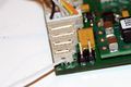
Closeup ground point
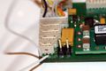
closeup grounding point detail for Bootloader uploading


The next step while your board is all connected and powered up is to type the commands for uploading the bootloader firmware.
TWOG Bootloader overview
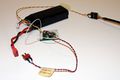
Everything ready to be powered-up now


In Linux
From your Paparazzi folder in Linux, type:
$ make upload_bl PROC=GENERIC
This will begin compiling your USB Bootloader and then attempt to transfer it to the Autopilot board. This will also assume you are using a USB -> Serial adapter for the connection. It uses /dev/ttyUSB0 by default. If your adapter is mapped to a different tty, you will need to modify the Makefile accordingly.

If everything is connected and setup correctly, after a while you will see the following messages

In Windows
If for some reason you need to program your autopilot board USB Bootloader in MS Windows you have to download the LPC2000 Flash Utility V2.2.3 or later. You will then prepare the autopilot board and start it in ISP bootloader state as described in the previous. This small utility will ony help uploading the Bootloder firmware. You will need to copy your compiled bl.hex file from Linux to your Windows OS. This file will be then uploaded.
Additional information
In depth info about the bootloader can be found on the Bootloader reference page. Also the page here explains some more]