Difference between revisions of "Lia"
Jump to navigation
Jump to search
(just link to Lisa/M v2.0 jumper configuration instead of duplicating info) |
|||
| Line 19: | Line 19: | ||
== Jumper Configuration == | == Jumper Configuration == | ||
There are a number of jumpers on Lia used to configure voltage levels and power input. Their locations and functions are identical to those on the Lisa/M v2.0. | There are a number of jumpers on Lia used to configure voltage levels and power input. Their locations and functions are identical to those on the Lisa/M v2.0.<br/> | ||
See the [[Lisa/M_v2.0#Jumper_Configuration|Jumper Configuration section on the Lisa/M v2.0 page]]. | |||
Revision as of 01:52, 22 March 2013
Lia is a lower cost version of Lisa/M first developed for inclusion with the Quadshot Mocha.
Differences from Lisa/M
- 0.1" pitch connectors instead of molex picoblade
- No CAN transceiver (footprint still present just not populated)
- No I2C2 level shifter (footprint still present just not populated)
- No 5V voltage regulator (footprint still present just not populated)
- No JTAG connector (footprint still present just not populated)
- Added servo power inline resistors (by default 0 ohm but can be changed to higher value for balancing the linear voltage regulators of the motor controllers)
Pictures
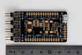
Lia V1.1 top side
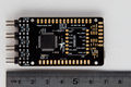
Lia V1.1 bottom side
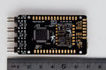
Lia V1.1 bottom side with Aspirin 2.1 nomag nobaro placed.


Jumper Configuration
There are a number of jumpers on Lia used to configure voltage levels and power input. Their locations and functions are identical to those on the Lisa/M v2.0.
See the Jumper Configuration section on the Lisa/M v2.0 page.