Difference between revisions of "Lia"
m (added link to Quadshot wiki) |
|||
| Line 17: | Line 17: | ||
Image:Lia_1.1_aspirin_bottom.jpg|Lia V1.1 bottom side with Aspirin 2.1 nomag nobaro placed. | Image:Lia_1.1_aspirin_bottom.jpg|Lia V1.1 bottom side with Aspirin 2.1 nomag nobaro placed. | ||
</gallery> | </gallery> | ||
=== Jumper Configuration === | |||
There are a number of jumpers on Lia used to configure voltage levels and power input. Their locations and functions are identical to those on the Lisa/M v2.0. The descriptions below thus apply to both boards. | |||
The default configuration is UART3 VCC at V_IN, UART1/2/5 VCC at +3V3, with the V_SERVO servo voltage rail NOT connected to the autopilot V_IN rail, allowing one to power the autopilot and servos separately. The +5V regulator is NOT bypassed, allowing a regulated +5V on listed headers and for the CAN transceiver and I2C level shifter. The V_BATT connector is NOT connected to V_IN, so one can attach a battery voltage to the V_BATT pin to measure the battery voltage, if so desired. | |||
<gallery widths=380px heights=205px> | |||
Image:LisaM_V2_0_top_jumpers_and_leds.png | Lisa/M v2.0 Top Jumpers and LEDs | |||
Image:LisaM_V2_0_bottom_jumpers.png | Lisa/M v2.0 Bottom Jumpers | |||
</gallery> | |||
<br style="clear:both"> | |||
{|border="1" cellspacing="0" style="text-align:center" cellpadding="2%" width="70%" | |||
|+'''Power Jumper Configuration''' | |||
!width="7%"|''Jumper''!!width="20%"|''Bus Connection''!!width="7%"|''Default''!!''Description'' | |||
|- | |||
|JP1||SERVO_BUS to V_IN||OPEN||Connects servo header voltage rail SERVO_BUS to autopilot input voltage V_IN rail | |||
|- | |||
|JP2||V_BATT to V_IN||OPEN||Connects I2C1/CAN rail V_BATT to autopilot input voltage V_IN rail | |||
|- | |||
|JP3||V_IN to +5V||OPEN||Connects autopilot input voltage V_IN rail to autopilot +5V rail, bypassing onboard 5V supply | |||
|} | |||
{|border="1" cellspacing="0" style="text-align:center" cellpadding="2%" width="70%" | |||
|+'''UART3 VCC Configuration''' | |||
!width="7%"|''Jumper''!!width="20%"|''Bus Connection''!!width="7%"|''Default''!!''Description'' | |||
|- | |||
|JP6||UART3_VCC to V_IN||style="background:black; color:white"|CLOSED||Connects UART3 connector VCC to autopilot input voltage V_IN rail | |||
|- | |||
|JP7||UART3_VCC to +3V3||OPEN||Connects UART3 connector VCC to autopilot +3V3 rail | |||
|} | |||
'''WARNING: UART3 GPS Connector is connected to V_IN, check your GPS input voltage before connecting!!!''' | |||
'''WARNING: DO NOT CLOSE BOTH JP6 AND JP7 SIMULTANEOUSLY!!!''' | |||
{|border="1" cellspacing="0" style="text-align:center" cellpadding="2%" width="70%" | |||
|+'''UART2 VCC Configuration''' | |||
!width="7%"|''Jumper''!!width="20%"|''Bus Connection''!!width="7%"|''Default''!!''Description'' | |||
|- | |||
|JP4||UART2_VCC to V_IN||OPEN||Connects UART2 connector VCC to autopilot input voltage V_IN rail '''SEE WARNING BELOW''' | |||
|- | |||
|JP5||UART2_VCC to +3V3||style="background:black; color:white"|CLOSED||Connects UART2 connector VCC to autopilot +3V3 rail | |||
|} | |||
'''WARNING: UART2 RX is NOT 5V TOLERANT. Thus, while possible to connect UART2_VCC to V_IN, DO NOT ATTEMPT THIS. Only use JP5 (the default). | |||
'''WARNING: DO NOT CLOSE BOTH JP4 AND JP5 SIMULTANEOUSLY!!!''' | |||
{|border="1" cellspacing="0" style="text-align:center" cellpadding="2%" width="70%" | |||
|+'''UART1 and UART5 VCC Configuration''' | |||
!width="7%"|''Jumper''!!width="20%"|''Bus Connection''!!width="7%"|''Default''!!''Description'' | |||
|- | |||
|JP8||UART1&5_VCC to V_IN||OPEN||Connects UART1 and UART5 connector VCC to autopilot input voltage V_IN rail | |||
|- | |||
|JP9||UART1&5_VCC to +3V3||style="background:black; color:white"|CLOSED||Connects UART1 and UART5 connector VCC to autopilot +3V3 rail | |||
|} | |||
'''WARNING: DO NOT CLOSE BOTH JP8 AND JP9 SIMULTANEOUSLY!!!''' | |||
There are additional jumpers on the board for expert or developer configurations, please see [[Lisa/M_v20#Schematic|schematic]] and [[Lisa/M_v20#Downloads|layout]] for more information. | |||
Revision as of 16:45, 21 March 2013
Lia is a lower cost version of Lisa/M first developed for inclusion with the Quadshot Mocha.
Differences from Lisa/M
- 0.1" pitch connectors instead of molex picoblade
- No CAN transceiver (footprint still present just not populated)
- No I2C2 level shifter (footprint still present just not populated)
- No 5V voltage regulator (footprint still present just not populated)
- No JTAG connector (footprint still present just not populated)
- Added servo power inline resistors (by default 0 ohm but can be changed to higher value for balancing the linear voltage regulators of the motor controllers)
Pictures
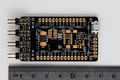
Lia V1.1 top side
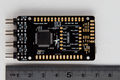
Lia V1.1 bottom side
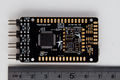
Lia V1.1 bottom side with Aspirin 2.1 nomag nobaro placed.


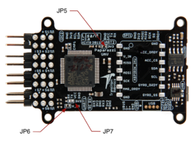
Jumper Configuration
There are a number of jumpers on Lia used to configure voltage levels and power input. Their locations and functions are identical to those on the Lisa/M v2.0. The descriptions below thus apply to both boards.
The default configuration is UART3 VCC at V_IN, UART1/2/5 VCC at +3V3, with the V_SERVO servo voltage rail NOT connected to the autopilot V_IN rail, allowing one to power the autopilot and servos separately. The +5V regulator is NOT bypassed, allowing a regulated +5V on listed headers and for the CAN transceiver and I2C level shifter. The V_BATT connector is NOT connected to V_IN, so one can attach a battery voltage to the V_BATT pin to measure the battery voltage, if so desired.
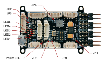
Lisa/M v2.0 Top Jumpers and LEDs
Lisa/M v2.0 Bottom Jumpers


| Jumper | Bus Connection | Default | Description |
|---|---|---|---|
| JP1 | SERVO_BUS to V_IN | OPEN | Connects servo header voltage rail SERVO_BUS to autopilot input voltage V_IN rail |
| JP2 | V_BATT to V_IN | OPEN | Connects I2C1/CAN rail V_BATT to autopilot input voltage V_IN rail |
| JP3 | V_IN to +5V | OPEN | Connects autopilot input voltage V_IN rail to autopilot +5V rail, bypassing onboard 5V supply |
| Jumper | Bus Connection | Default | Description |
|---|---|---|---|
| JP6 | UART3_VCC to V_IN | CLOSED | Connects UART3 connector VCC to autopilot input voltage V_IN rail |
| JP7 | UART3_VCC to +3V3 | OPEN | Connects UART3 connector VCC to autopilot +3V3 rail |
WARNING: UART3 GPS Connector is connected to V_IN, check your GPS input voltage before connecting!!!
WARNING: DO NOT CLOSE BOTH JP6 AND JP7 SIMULTANEOUSLY!!!
| Jumper | Bus Connection | Default | Description |
|---|---|---|---|
| JP4 | UART2_VCC to V_IN | OPEN | Connects UART2 connector VCC to autopilot input voltage V_IN rail SEE WARNING BELOW |
| JP5 | UART2_VCC to +3V3 | CLOSED | Connects UART2 connector VCC to autopilot +3V3 rail |
WARNING: UART2 RX is NOT 5V TOLERANT. Thus, while possible to connect UART2_VCC to V_IN, DO NOT ATTEMPT THIS. Only use JP5 (the default).
WARNING: DO NOT CLOSE BOTH JP4 AND JP5 SIMULTANEOUSLY!!!
| Jumper | Bus Connection | Default | Description |
|---|---|---|---|
| JP8 | UART1&5_VCC to V_IN | OPEN | Connects UART1 and UART5 connector VCC to autopilot input voltage V_IN rail |
| JP9 | UART1&5_VCC to +3V3 | CLOSED | Connects UART1 and UART5 connector VCC to autopilot +3V3 rail |
WARNING: DO NOT CLOSE BOTH JP8 AND JP9 SIMULTANEOUSLY!!!
There are additional jumpers on the board for expert or developer configurations, please see schematic and layout for more information.