Difference between revisions of "Compiling"
| Line 35: | Line 35: | ||
=== JTAG Flashing === | === JTAG Flashing === | ||
You should have [[DevGuide/OpenOCD|OpenOCD]] already installed. | |||
[[Lisa/L]] has an onboard [[JTAG]] while [[Lisa/M]] needs an external JTAG. | |||
Either click upload the [[Paparazzi_Center|Paparazzi Center]] to compile and upload or do it from the commandline: | |||
make AIRCRAFT=Microjet_LisaM ap.upload | |||
[[Lisa/M v1.0]] defaults to '''FLASH_MODE=JTAG''', while [[Lisa/M v2.0]] defaults to ''FLASH_MODE=DFU''' using the [[luftboot]] usb bootloader. | |||
During an upload the JTAG RxTx LEDs should blink. | |||
=== Start the usb bootloader on an LPC21xx based board === | === Start the usb bootloader on an LPC21xx based board === | ||
| Line 101: | Line 98: | ||
Connect the usb cable and power on the autopilot to receive the code. The code will switch the USB to emulate a serial port that you can access at '''/dev/ttyACMx'''. Windows user can extract the usbser.sys file from .cab file in C:\WINDOWS\Driver Cache\i386 and store it somewhere (C:\temp is a good place) along with the [[Media:Usbser.zip|usbser.inf]] file. Windows then creates an extra COMx port that you can use in a terminal program or with ucenter. | Connect the usb cable and power on the autopilot to receive the code. The code will switch the USB to emulate a serial port that you can access at '''/dev/ttyACMx'''. Windows user can extract the usbser.sys file from .cab file in C:\WINDOWS\Driver Cache\i386 and store it somewhere (C:\temp is a good place) along with the [[Media:Usbser.zip|usbser.inf]] file. Windows then creates an extra COMx port that you can use in a terminal program or with ucenter. | ||
To use the USB tunnel make sure you first power the autopilot before connecting USB not to end up in the USB bootloader. | To use the USB tunnel make sure you first power the autopilot before connecting USB not to end up in the USB bootloader. | ||
[[Category:Software]] [[Category:User_Documentation]] [[Category:Developer_Documentation]] | [[Category:Software]] [[Category:User_Documentation]] [[Category:Developer_Documentation]] | ||
Revision as of 05:44, 7 February 2013
Introduction
The goal of this part of the documentation is to give you insight in how to give your Autopilot board a Brain. Airborne autopilot code, flight plans and configuration settings are compiled into a single file, sometimes referred to as a binary image. After compilation this file is transferred to the Autopilot board micro-controller flash ROM through use of an USB cable. Note that most tuning and flight plan parameters can be changed in-flight but after each power cycle, the autopilot reverts to the original settings. Permanent changes are made by recompiling the airborne code and it's new configurations settings, and re-upload this to the autopilot board. It may sound complicated but in fact it is quite simple if you follow the steps below.
Flashing
USB flashing

If the autopilot senses a connected USB cable during power-on, it will wait to receive a firmware image rather than booting normally. The firmware can be compiled and flashed by several means, the simplest way using the Paparazzi Center, the traditional way being:
make AIRCRAFT=myplane clean_ac ap.upload
(where myplane is the name of your airframe as defined in conf/conf.xml)
This command erases any compiled autopilot code from the PC, recompiles everything from scratch, and then sends it to the autopilot. Variations include:
- make AIRCRAFT=myplane sim
- Compiles your code for use in the simulator - note that "clean_ac" will remove this code, so the simulator code must be rebuilt each time a clean has been performed.
- make AIRCRAFT=myplane fbw.upload
- This is needed when configuring the separate "fly by wire" MCU on the Classix autopilot.
- make AIRCRAFT=myplane ap
- This will simply build the portions of autopilot code that have changed since the last compile without attempting to flash. Note: this method may not detect certain changes (i.e. changes to the airframe makefile section or CVS updated code).
- make AIRCRAFT=myplane ap.upload FLASH_MODE=IAP
- Specifies USB flashing. This should be specified at the top of the makefile section of your airframe file but can be overridden here. Use FLASH_MODE=IAS for serial flashing.
Serial Flashing
You can also flash via serial cable or modem, but it takes a longer time. You can't just consider the baud rate to estimate the duration of the operation are there are many exchanges in the flashing protocol and the com latency over RF becomes significant.
- make AIRCRAFT=myplane ap.upload FLASH_MODE=ISP
Or add <configure name="FLASH_MODE" value="ISP"/> to the firmware section of your airframe file.
Example: make AIRCRAFT=NAVGOV3 ap.upload FLASH_MODE=ISP
NOTES:
- Make sure you connect your serial device to UART0
- Make sure you pull P0.14 boot pin low on power on to enable the LPC ISP mode
JTAG Flashing
You should have OpenOCD already installed. Lisa/L has an onboard JTAG while Lisa/M needs an external JTAG.
Either click upload the Paparazzi Center to compile and upload or do it from the commandline:
make AIRCRAFT=Microjet_LisaM ap.upload
Lisa/M v1.0 defaults to FLASH_MODE=JTAG', while Lisa/M v2.0 defaults to FLASH_MODE=DFU using the luftboot usb bootloader. During an upload the JTAG RxTx LEDs should blink.
Start the usb bootloader on an LPC21xx based board
Connect an USB cable to the USB port on the autopilot board.
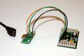
Board to mini USB connect
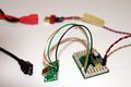
Make sure you have a connector for power (Don't power up yet!)
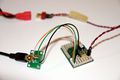
Connect USB to PC and Board
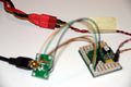
only now, power up the board


Check if the usb bootloader is installed on an LPC21xx based board
Now if you type the following command in your terminal...
$ dmesg | tail
..you should see messages that look like:
[82342.968031] usb 5-1: new high speed USB device using ehci_hcd and address 24
Which confirms that your device is powered up and working, and ready to accept new airborne code. In case you do not see this message, check your battery voltage and connections and make sure the cables are not broken.
When you upload in the Paparazzi Center it will print out messages. The important bit of output is:
   Found USB device
   BootROM code: 2.12
   Part ID: 0x0402FF25 (LPC2148, 512k Flash, 32k+8k RAM)
   BootLoader version: 1.3
Which confirms that your device has the bootloader functioning...
Installing the tunnel for direct access to the GPS
This completely replaces the normal autopilot code (leaving the USB bootloader intact) with a simple serial-to-serial pass-thru that essentially connects the GPS serial port directly to the modem serial port or a USB-to-serial connection that creates a USB serial port that goes to GPS port or modem port. Use this only to gain direct access to the GPS for testing/configuration with U-Center or other software.
You have to add the tunnel targets to your airframe file if you want to use them:
 <firmware name="setup">
   <target name="tunnel" board="twog_1.0" />
   <target name="usb_tunnel_0" board="twog_1.0" />
 </firmware>
UART tunnel
Use this if you have a serial cable to connect. The LEDs will blink when data is transferred. Type the following command from your paparazzi folder, substituting the name of your airframe and paying attention to case sensitivity:
make AIRCRAFT=myplane tunnel.upload
Connect the USB cable and power on the autopilot to receive the code.
This can be done without the USB bootloader by appending FLASH_MODE=ISP to the command line (specifying ISP serial loading). This will require a serial cable connection (i.e. FTDI USB-to-TTL). WARNING! Installing tunnel code with the ISP method will erase any USB bootloader code. Make sure you are able to install a bootloader yourself.
USB tunnel
This can be done without a serial cable just by having USB. The LEDs will blink when data is transferred. It can connect to either serial port on the autopilot (for Tiny 2.11: uart0=gps, uart1=modem). To connect USB to the gps type the following command from your paparazzi folder, substituting the name of your airframe and paying attention to case sensitivity:
make AIRCRAFT=myplane usb_tunnel_0.upload
Connect the usb cable and power on the autopilot to receive the code. The code will switch the USB to emulate a serial port that you can access at /dev/ttyACMx. Windows user can extract the usbser.sys file from .cab file in C:\WINDOWS\Driver Cache\i386 and store it somewhere (C:\temp is a good place) along with the usbser.inf file. Windows then creates an extra COMx port that you can use in a terminal program or with ucenter. To use the USB tunnel make sure you first power the autopilot before connecting USB not to end up in the USB bootloader.