YAPA/v1.0
Revision as of 03:15, 11 December 2011 by P0rc0 r0ss0 (talk | contribs)
YAPA v1
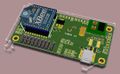
Rendering
Top side
Bottom side


Features
- Basic Design very similar to Twog_v1 (uses same autopilot configuration file 'tiny2_1_1.h')
- 100mil headers instead of the (nice and lighter) Molex connectors
- Support Holes (e.g. use M3 bobbins: [1])
- 5 x Analog 3.3V inputs with 2 of them low pass filtered
- (Optional) 2x RS232/RS422/RS485/3.3TLL serial ports for connecting virtually any serial device (if using xbee: then 1 port)
- (Optional) Onboard (optional) Xbee Modem
- 8 x PWM outputs on standard 1/10th inch headers
- 1 x R/C receiver PPM frame input
- 1 x SPI bus
- 1 x I2C bus
- 1 x USB (client) with either onboard mini-usb AND/OR remotely located USB Plug
- 2x 3.3v / 1A linear regulator for Processor and for XBee modem separated for safety
- 1 x status LEDs
- 80.0 x 40.0mm
- 23 grams including 2.4GHz Xbee Pro, all 100mil headers, usb connector, 2.5Amp 5V DCDC and serial converter
- 1 power switch with current limiter
- 2 layers PCB design, 0603 components
- (Optional) onboard 5v / 2.25A switching power supply (input voltage range 6.1v → 18v)
- 3 power options using a jumper/bridge to connect the servo power rail to the autopilot 5V power rail:
- In the case of few very low power servo's: you power your servo's from the autopilot power (not recommended: in any case check to make sure all servo's together never ever use more than 1.5 amp even when blocked)
- In the case of a high quality external BEC: you can omit the onboard regulator and power everything from the BEC.
- Otherwise: separated onboard autopilot 5V power and externally supplied servo power
Architecture
