|
|
| Line 1: |
Line 1: |
| = Introduction = | | = Intro = |
|
| |
|
| If you consider yourself a developer this flexible piece of UAS hardware is for you. If you enjoy writing software and consider yourself an early adopter this is the board to use. Have fun implementing and extending the already great features. To show of your work and also to ask questions, you are welcomed on the paparazzi mailinglist, this Wiki and the freenode paparazzi IRC channel. This nice piece of hardware can be used for various purposes. Ofcourse as an Autopilot board, but only by uploading another firmware also a servo extension board and more. A good idea of how this nice piece of hardware looks like is shown on the Photos here. If you are not so interested in all of this at the moment since you just have this shiny new board on you desk and want to connect and fly the thing, then go to the page [[Lisa/M/Tutorial/FixedWing| using the board as an '''Autopilot''' for an airplane]] or go [[Lisa/M/Tutorial/RotorCraft|here for uses a an '''Autopilot''' in a quadrotor]]
| | This article is meant as a tutorial on how to assemble, wire up and mount devices in a fixed wing aircraft based on [[Lisa/M]] for a maiden flight on Autopilot. We will use a Multiplex Mentor as example. |
|
| |
|
| [[Image:Lisa_M_V1_0_top_with_coin.jpg|thumb|Lisa/M V1.0 top view]]
| | For this we need: |
| [[Image:Lisa_M_V1_0_bottom_with_coin.jpg|thumb|Lisa/M V1.0 bottom view]]
| |
| [[Image:Lisa_M_V1_0_top.jpg|thumb|Lisa/M V1.0 top view]]
| |
| [[Image:Lisa_M_V1_0_bottom.jpg|thumb|Lisa/M V1.0 bottom view]]
| |
|
| |
|
| = Initial Setup =
| | 1x Mentor complete set |
|
| |
|
| If you want to just simply setup the board for use as an Autopilot and are looking for information about how to get the Lisa/M board up and running and where to connect other hardware just follow the link below if you have that great Lisa/M board and want to get get it airborne fast.
| | 1x Receiver |
|
| |
|
| * [[Lisa/M/Tutorial/FixedWing]] - for an airplane, glider or flying wing;
| | 1x uBlox LEA5 Helix module |
| * [[Lisa/M/Tutorial/RotorCraft]] - for everything that flies via moving blades: helicopters, quadrocopters or something alike.
| |
|
| |
|
| = Features = | | = Setup Hardware = |
|
| |
|
| Lisa/M is based on the 64 pins STM32F105RC processor featuring 64k of RAM and 256k of FLASH. All the pins are exposed, providing access to the complete set of the STM32 peripherals.
| | == IMU == |
| NOTE: This MCU is different from LISA/L. Lisa/L is based on the 64 pins STM32F103RE processor featuring 64k of RAM and 512k of FLASH, which is [http://www.st.com/internet/mcu/product/164485.jsp high-density performance line family] where STM32F105RC of LISA/M is [http://www.st.com/internet/mcu/product/221023.jsp connectivity line family].
| |
|
| |
|
| == Overview ==
| | The [[LisaM|Lisa/M]] can be purchased with the [[Inertial_Measurement_Units#Aspirin_IMU|Aspirin IMU]] already soldered to it. Otherwise, you can solder an [[Inertial_Measurement_Units#Aspirin_IMU|Aspirin IMU]] on it yourself. |
|
| |
|
| * Single [http://www.st.com/stm32 STM32 MCU]
| | == GPS == |
| * Pressure sensor [http://www.bosch-sensortec.com/content/language1/html/3477.htm BMP085]
| |
| * 7 x Analog input channels
| |
| * 3 x Generic digital in-/out-puts
| |
| * 2 x 3.3V TTL UART (5V tolerant)
| |
| * 7 x Servo PPM outputs
| |
| * 1 x CAN bus
| |
| * 1 x [http://en.wikipedia.org/wiki/Serial_Peripheral_Interface SPI] bus
| |
| * 1 x [http://en.wikipedia.org/wiki/I2c I<sup>2</sup>C] bus
| |
| * 1 x Micro USB
| |
| * 4 x status LEDs with attached test point
| |
| * 10.8 grams (0.4 oz) (with Aspirin IMU mounted)
| |
| * 9.9 grams (0.35 oz) (without Aspirin IMU mounted)
| |
| * ~33mm x ~56mm x ~10mm
| |
| * 4 layers PCB design
| |
|
| |
|
| with mounted IMU has the following additional sensors on board:
| | On connector UART1 we will connect the GPS receiver. A [[GPS#u-Blox_LEA_Series_Receivers|uBlox LEA-5H]] will be uses in the basic setup |
|
| |
|
| * 3 Axis Gyroscope
| | == Servos == |
| * 3 Axis Accelerometer
| |
| * 3 Axis Magnetometer
| |
|
| |
|
| The pressure sensor is mounted directly on the board as this sensor is not provided by Aspirin. Exept for a GPS unit you have all necessary sensors for full attitude and altitude stabilization in an extremely small package. Adding only an external GPS unit, it is a full fledged Autopilot.
| | === ESC === |
|
| |
|
| == Footprint ==
| | The ESC which stand for Electronic Speed Control to contol the motor speed will be connected to servo pins S1 |
|
| |
|
| This autopilot is very small. The footprint is only 33mm by 56mm by 10mm including the servo connector pins. It will fit in a small UAS very well. There is a spot for mounting the [http://paparazzi.enac.fr/wiki/AspirinIMU Aspirin IMU] directly on board.
| | === Aileron === |
|
| |
|
| == MCU ==
| | To Pin S2 we connect the left aileron servo. Left side is left is as seen from the back of the airframe. And to pin S5 we connect the right aileron cable |
|
| |
|
| In brief, the STM32 features 3 USARTS, 2 SPI, 2 I2C, 1 CAN, a plethora of timers, ADCs and a generic DMA able to serve all of them. On the board, a number of the communication interfaces are level shifted with user selectable voltage to allow interfacing with all kind of peripherals.
| | === Elevator === |
|
| |
|
| == Onboard IMU ==
| | On Pin S3 the Elevator servo cable |
|
| |
|
| The Lisa/M comes with [[AspirinIMU|Aspirin IMU]] mounted, for easy attitude estimation in the smallest package possible.
| | === Rudder === |
|
| |
|
| == JTAG ==
| | On Pin S4 the rudder servo cable |
|
| |
|
| * [[JTAG]] description;
| | == RC receiver == |
| * General [[Dev/Debugging|debugging information]];
| |
| * [[DevGuide/JTAG-Debug|JTAG usage]], includes Eclipse uplink tutorial.
| |
|
| |
|
| = Hardware Revision History =
| | To be able to test your UAS a RC receiver comes in very handy. One must realize without a receiver an well tuned airframe can fly very well, however for initial tests adding a receiver makes life so much easier. The documentation here will describe how to connect and setup such an RC receiver. |
|
| |
|
| == Changes between v0.1 and v1.0 == | | === PPM receiver === |
| * Switched to stm32f105 to be able to use usb and can at the same time
| |
| * Added alternative use of the adc lines as led output
| |
| * ...
| |
|
| |
|
| == Changes between v1.0 and v1.1 ==
| | A modified RC receiver with full PPM out can be used to control the AP board from the ground. How to get a receiver with full PPM out or modify an existing one [http://paparazzi.enac.fr/wiki/RC_Receivers_and_Radios#PPM_Based_Systems can be found here.] |
| * Removed pull-ups on the USB gpio
| |
| * Removed pull-ups on the CAN gpio
| |
| * Connected usb_vbus to pa9 (needed by the USBotg)
| |
| * Removed USB pullup transistor as usbotg has a built in pullup
| |
| * Swapped UART1 with UART3 (uart1 was used for gps and pa9 was it's tx line, to be able to talk to the gps unit uart3 is a better choice, as uart1 only has an rx line now it is a better choice for spektrum RX modules)
| |
| * Removed USART3 TX gpio from the GPIO connector and moved to the GPS connector
| |
| * Added voltage selector jumpers to the RC RX connector; to enable powering of 3v3 or an 5v receivers
| |
| * Replaced vertical board solution with through hole servo pin headers (easier assembly)
| |
| * Servo connectors are in groups of two; for easier assembly
| |
| * Servo VBUS is connected together on all four layers; for lower resistance
| |
| * Moved LED's from under the analog2 connector; to be able to populate LED's and the connector
| |
| * Moved the RC RX connector a bit; to prevent crashing with the jtag plug
| |
| * Added one additional servo connector; now we have all 8 accessible through the standard servo connectors
| |
| * Fixed servo channel labeling to start at '''S0''' as it is the case on TWOG and Tiny autopilot boards
| |
| * Added secondary through hole picoblade USB connector for easier routing of USB inside an airframe
| |
| * ...
| |
|
| |
|
| == Changes between v1.1 and v2.0 ==
| | PPM is at the moment sharing a line with servo6, because it's the way it was wired on a Lisa/L board. It would be trivial to adapt the driver to use another line. look at sw/airborne/arch/stm32/subsystems/radio_control/ppm_arch.c . If you manage to do so please adjust the text on this page also. |
| * Lot's of silkscreen improvements
| |
| * Added attributes to all parts to make the usage of bom-ex ulp possible.
| |
| * Improved routing to allow teardropping
| |
| * Fixed stm32f1, f2 and f4 compatibility circuit. (has to jump to ground not to 3v3)
| |
| * Connected existing UART RX pullups to the respective connector power pins instead of 3v3. To prevent connecting 5V over IO pin to the 3v3 power rail.
| |
| * Added pullups on all UART RX lines to prevent undesired floatation.
| |
| * LED's are connected to 3v3 now. To make sure we don't have an issue with voltage tolerance on the gpio pins.
| |
| * ...
| |
|
| |
|
| = Hardware update requests = | | === Satellite Receiver === |
| * REQ: Replace BMP085 with MS5611 (the MS5611 seems to be better in performance then the BMP but it is more expensive and seems to be more difficult to obtain.
| |
| ** A: It is considered as an update to a future version of lisa/m not V2.0 --[[User:Esden|Esden]] 02:24, 18 November 2011 (CET))
| |
|
| |
|
| * REQ: Replace 7 Pin CAN with molex with something less risky to be inserted in 7 Pin SPI in relation to powering the board via CAN molex.
| | Connecting a 2.4GHz Spectrum or compatible receiver |
|
| |
|
| * REQ: Separate spot for external power if powered via separate battery. Realizing we can via Servo ports by Bridge J1 but still like to measure board voltage then and have a way to add power without mistakenly inject CAN Molex into SPI.
| | [[Image:Lisa_M_V1_0_satellite_receiver_connection_labeled.png|500px]] |
|
| |
|
| = Architecture =
| | It is very well possible to connect another 2.4Ghz receiver, however the software to interact with that device must at the moment be written by oneself. The advantage of Opensource is that it is possible. Sharing your coding work would be great and in line with the GPL license. |
|
| |
|
| = Usage scenarios = | | == Telemetry== |
|
| |
|
| For regular Autopilot boards a full Lisa/M board is needed. For some scenarios just a basic Lisa/M without [[Inertial_Measurement_Units|IMU]] and [[Airspeed_sensor|pressure sensor]] is needed, this makes the board cheaper of course.
| | An [[Modems#Digi_XBee_Pro_ZB_.2F_ZNet_2.5_.28.22Series_2.22.29|XBee XSC]] wireless data module will be used to enable to receive telemetry data. While not needed for fully autonomous flight it is very beneficial to have telemetry data. We will connect the transmitter to connector UART2 |
|
| |
|
| == As a basic Autopilot == | | == Power == |
|
| |
|
| To use the Lisa/M as an autopilot, we need to attach a GPS receiver. A nice [[GPS#u-Blox_LEA_Series_Receivers|uBlox LEA-5H]] or newer will perform great.
| |
|
| |
|
| == As and advanced Autopilot == | | === Jumpers === |
|
| |
|
| Also an external airspeedsensor like the Eagletree would enhance a fixedwing airframe. Ofcourse an extention cable from microUAS to Mini USB to the outside of the airframe is very practical.
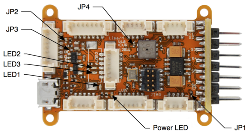
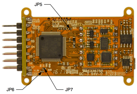
| | [[Image:LisaM_V1_0_top_jumpers_and_leds.png|500px]][[Image:LisaM_V1_0_bottom_jumpers.png|450px]] |
| Currently UART3 outlet is used to talk to GPS reciever.
| |
|
| |
|
| == As a servo extender ==
| | It is possible to reconfigure the electrical system on [[Lisa/M]] using the supply jumpers. On the boards the Jumper are not real jmper but a spot where we can solder or unsolder a "Bridge" to make or break the connection. In our case the ESC will supply both the servos and the board with power from the main battery. This is the default setup of [[Lisa/M]], so there is no need to solder anything on the board. |
|
| |
|
| Sometimes being able to steer seven actuators is just not enough. One need for example flaps that enhance aileron or an airbrake and automatic landingfacility. Maybe special ACL lights, or four cameras with zoom. By using a coupled second basic Lisa/M and connect this to the master AP board we can extend our amount of servos.
| | * JP1 connects the servo power rail to V_IN rail. |
| | * JP2 connects the battery rail (used by default only for battery voltage measurement) to the V_IN rail. |
| | * JP3 bypasses the +5V voltage regulator and connects V_IN to the +5V rail. |
| | * JP4 connects the V_IN rail to the VCC pin on the UART2 connector. |
| | * JP5 connects the +3V3 rail to the VCC pin on the UART2 connector. |
| | * JP6 connects the V_IN rail to the VCC pin on the UART1 connector. |
| | * JP7 connects the +3V3 rail to the VCC pin on the UART1 connector. |
|
| |
|
| == As a Safety Pilot Device == | | = Setup Software = |
|
| |
|
| To provide an extra safety level required in some UAS challenges a second Lisa board can make it easy to adhere to the rules for such a challenge.
| | == Bootloader == |
|
| |
|
| == As a Data Logger ==
| | To awake the hardware from sleep and activate the "brain" a so called "bootloader" is used. At the moment there is no bootloader code released yet for Paparazzi and this type of board. If there was, you would not need [[JTAG]] to change the software in your [[Lisa/M]] and only a USB cable would suffice to upload a new flight plan (just as it is now with a LPC21-based Paparazzi Autopilot board like the [[Twog_v1|TWOG]].) If you are good at writing bootloaders for the STM please add your code to the Paparazzi repository. |
|
| |
|
| Maybe you have a need only to log all kinds of data, like temperature, volts, amps, height, airspeed only. For this we can setup a Lisa/M board. Then we are flexible and add whatever sensors we want. Collecting this data can be to a storage medium like an micro SD card. Sometimes there is no need for realtime data collection but just for storing a huge dataset.
| | == Uploading Firmware == |
|
| |
|
| == As a Camera controller ==
| | For the board to perform some sort of action, a "Brain" a.k.a Firmware must be uploaded to the board. This is done by way of a JTAG cable. If you do not have wuch a cable, it is not possible to upload your flightplan firmware to the board. You can order this cable a various hardware suppiers. The Cable design is also opensource, you could opt to make one yourself, but that is not trivial. |
| On some models that do not require much servos (for example - flying wing with only 3 chanels used), spare channels can be used for camera control.
| |
|
| |
|
| == As a Airframe Tracker == | | == IMU Calibration == |
|
| |
|
| A remote antenna or camera on a tripod is on of the may option to use a Lisa/M Board. The remote device Must be able to get data from the pale in one form or another.
| | If you didn't make the board yourself, then you probably got a calibration file (.xml) from your board supplier. If you didn't receive a calibration file then follow the steps for [http://paparazzi.enac.fr/wiki/ImuCalibration onboard IMU calibration]. |
|
| |
|
| = Pinout = | | = Pre-flight Checklist= |
|
| |
|
| Pins Name and Type are specified with respect to the Autopilot Board
| | Double-check that you connected everything correctly. Then switch on your transmitter and power up your board. |
|
| |
|
| [[Image:LisaM_V1_0_top_labeled.png|700px]]
| | = Flying = |
|
| |
|
| = Schematic =
| | This page is not the one to find and information about that. A look around on this wiki or elswhere on the internet can help you out. |
|
| |
|
| <gallery>
| | [[Category:User_Documentation]] |
| Image:Lisa_m_v1_0_sheet_1.png | LisaM V1.0 Schematic Sheet 1/3
| |
| Image:Lisa_m_v1_0_sheet_2.png | LisaM V1.0 Schematic Sheet 2/3
| |
| Image:Lisa_m_v1_0_sheet_3.png | LisaM V1.0 Schematic Sheet 3/3
| |
| </gallery>
| |
| | |
| = Electrical Connections to the Airborne Equipment =
| |
|
| |
| == Receivers ==
| |
| There is spectrum parser available already.
| |
| Also UART pins can be used as general purpose I/O to be used for PPM input.
| |
| | |
| Additionally [http://www.aerofu.com/index.php?main_page=product_info&cPath=1&products_id=50 PPM encoder] can be used to avoid receiver hardware modification.
| |
| | |
| = PCB =
| |
| | |
| == Gerber & Drill Files ==
| |
| | |
| = Assembly =
| |
| | |
| == Components Layout ==
| |
| | |
| == Mechanical drawing ==
| |
| | |
| [[Image:LisaM_V1_0_top_mechanical.png|500px]]
| |
| | |
| === Bill Of Material ===
| |
| | |
| | |
| [[Category:User_Documentation]] [[Category:Hardware]] | |
| | |
| = PCB and assembled boards suppliers =
| |
| | |
| For private companies and enthusiast Paparazzi hardware suppliers, see [[Get_Hardware|Get Hardware]] page.
| |
| | |
| = Downloads =
| |
| | |
| The CAD files are also available from the [http://svn.sv.gnu.org/svn/paparazzi/paparazzi-hardware/trunk/lisa_m/ paparazzi-hardware svn server]
| |
| | |
| '''Schematics'''
| |
| * [[Image:Lisa m v1 0 sheet1 of 3.pdf]]
| |
| * [[Image:Lisa m v1 0 sheet2 of 3.pdf]]
| |
| * [[Image:Lisa m v1 0 sheet3 of 3.pdf]]
| |
| | |
| '''Source files'''
| |
| :*download ''LisaM v1.00 Eagle design (zip)''
| |
| '''Gerber & Drill files'''
| |
| :*download '' gerber & drill files (zip)''
| |
| '''Assembly files'''
| |
| :*download ''(pdf)''
| |
| :*download '' (zipped .xls file)''
| |
Intro
This article is meant as a tutorial on how to assemble, wire up and mount devices in a fixed wing aircraft based on Lisa/M for a maiden flight on Autopilot. We will use a Multiplex Mentor as example.
For this we need:
1x Mentor complete set
1x Receiver
1x uBlox LEA5 Helix module
Setup Hardware
IMU
The Lisa/M can be purchased with the Aspirin IMU already soldered to it. Otherwise, you can solder an Aspirin IMU on it yourself.
GPS
On connector UART1 we will connect the GPS receiver. A uBlox LEA-5H will be uses in the basic setup
Servos
ESC
The ESC which stand for Electronic Speed Control to contol the motor speed will be connected to servo pins S1
Aileron
To Pin S2 we connect the left aileron servo. Left side is left is as seen from the back of the airframe. And to pin S5 we connect the right aileron cable
Elevator
On Pin S3 the Elevator servo cable
Rudder
On Pin S4 the rudder servo cable
RC receiver
To be able to test your UAS a RC receiver comes in very handy. One must realize without a receiver an well tuned airframe can fly very well, however for initial tests adding a receiver makes life so much easier. The documentation here will describe how to connect and setup such an RC receiver.
PPM receiver
A modified RC receiver with full PPM out can be used to control the AP board from the ground. How to get a receiver with full PPM out or modify an existing one can be found here.
PPM is at the moment sharing a line with servo6, because it's the way it was wired on a Lisa/L board. It would be trivial to adapt the driver to use another line. look at sw/airborne/arch/stm32/subsystems/radio_control/ppm_arch.c . If you manage to do so please adjust the text on this page also.
Satellite Receiver
Connecting a 2.4GHz Spectrum or compatible receiver

It is very well possible to connect another 2.4Ghz receiver, however the software to interact with that device must at the moment be written by oneself. The advantage of Opensource is that it is possible. Sharing your coding work would be great and in line with the GPL license.
Telemetry
An XBee XSC wireless data module will be used to enable to receive telemetry data. While not needed for fully autonomous flight it is very beneficial to have telemetry data. We will connect the transmitter to connector UART2
Power
Jumpers
It is possible to reconfigure the electrical system on Lisa/M using the supply jumpers. On the boards the Jumper are not real jmper but a spot where we can solder or unsolder a "Bridge" to make or break the connection. In our case the ESC will supply both the servos and the board with power from the main battery. This is the default setup of Lisa/M, so there is no need to solder anything on the board.
- JP1 connects the servo power rail to V_IN rail.
- JP2 connects the battery rail (used by default only for battery voltage measurement) to the V_IN rail.
- JP3 bypasses the +5V voltage regulator and connects V_IN to the +5V rail.
- JP4 connects the V_IN rail to the VCC pin on the UART2 connector.
- JP5 connects the +3V3 rail to the VCC pin on the UART2 connector.
- JP6 connects the V_IN rail to the VCC pin on the UART1 connector.
- JP7 connects the +3V3 rail to the VCC pin on the UART1 connector.
Setup Software
Bootloader
To awake the hardware from sleep and activate the "brain" a so called "bootloader" is used. At the moment there is no bootloader code released yet for Paparazzi and this type of board. If there was, you would not need JTAG to change the software in your Lisa/M and only a USB cable would suffice to upload a new flight plan (just as it is now with a LPC21-based Paparazzi Autopilot board like the TWOG.) If you are good at writing bootloaders for the STM please add your code to the Paparazzi repository.
Uploading Firmware
For the board to perform some sort of action, a "Brain" a.k.a Firmware must be uploaded to the board. This is done by way of a JTAG cable. If you do not have wuch a cable, it is not possible to upload your flightplan firmware to the board. You can order this cable a various hardware suppiers. The Cable design is also opensource, you could opt to make one yourself, but that is not trivial.
IMU Calibration
If you didn't make the board yourself, then you probably got a calibration file (.xml) from your board supplier. If you didn't receive a calibration file then follow the steps for onboard IMU calibration.
Pre-flight Checklist
Double-check that you connected everything correctly. Then switch on your transmitter and power up your board.
Flying
This page is not the one to find and information about that. A look around on this wiki or elswhere on the internet can help you out.


