Twog v1
Jump to navigation
Jump to search
!! WARNING !!
THIS IS A PRELIMINARY DESIGN, IT HAS NOT BEEN TESTED YET.
DO NOT USE FOR MASS PRODUCTION AS LONG AS THIS MESSAGE REMAIN.

Hardware Revision History
| Version # | Release Date | Release Notes |
|---|---|---|
| v1.00 | 04/2008 | Initial release of Twog v1 |
Features
- Single LPC2148 MCU
- 8 x Analog input channels 0V - 3.3V (2 channels with optional on-board resistor bridge)
- 1 x 3.3V TTL UART (5V tolerant)
- 8 x PWM outputs
- 1 x R/C receiver PPM frame input
- 1 x SPI bus
- 1 x I2C bus
- 1 x USB (client)
- 5V/2.5A switching power supply & 3.3V/1A linear regulator
- 3 x status LEDs with attached test point
- ?? grams
- 40.2 x 30.5mm (1.6" x 1.2")
- 2 layers PCB design, 0603 components
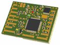
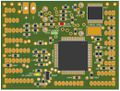
Twog v1.00 3D top view
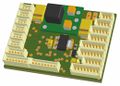
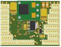
Twog v1.00 3D bottom view

Architecture
Pinout
Pins Name and Type are specified with respect to the Autopilot Board
Schematic
PCB
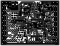
Twog v1.00 PCB top copper
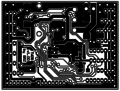
Twog v1.00 PCB bottom copper


Gerber & Drill Files
Download Twog v1.00 gerber & drill files (zip)
RS274X, units = Inches, format = 2:5
- Twog_v1-00.GTO (Top Component Print Layer)
- Twog_v1-00.GTS (Top Solder Mask)
- Twog_v1-00.GTL (Top Copper Layer)
- Twog_v1-00.GBL (Bottom Copper Layer)
- Twog_v1-00.GBS (Bottom Solder Mask)
- Twog_v1-00.DRI (NC XY coordinates & Drill tools sizes)
Possible PCB Manufacturers
Assembly
Components Layout
Top components Layout
Bottom components Layout
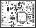
Top components details
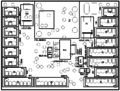
Bottom components details


Bill Of Material
Download Twog v1.00 Bill Of Material (zipped .xls file)
Downloads
Source files
Gerber & Drill files
Assembly files