NavGo v3

Hardware Revision History
| Version # | Release Date | Release Notes |
|---|---|---|
| v3 | 07/2012 | Minor PCB modifications |
| v2 | 11/2011 | Barometer redesign |
| v1 | 08/2011 | Initial release of NavGo |
Features
- NXP LPC2148 MCU based
- 1 x Triple axis Digital Gyroscope (Invensense ITG-3200)
- 1 x Triple axis Digital Accelerometer (Analog Devices ADXL345)
- 1 x Triple axis Magnetometer (Honeywell HMC5883L)
- 1 x Digital Baro-altimeter (Freescale MPXA6115 pressure sensor + Microchip MCP3550-60 22bits ADC)
- 1 x R/C receiver PPM frame input
- 2 x UART (TTL 3.3V, 5V tolerant)
- 2 x I2C bus
- 1 x SPI bus
- 1 x USB (client)
- 2 x General Purpose I/O or Analog input channels (0V - 3.3V)
- 5v / 1.5A switching power supply (input voltage range 5.5V min → 16.0v max)
- 3.3v / 1A linear regulator
- 4 x status LEDs
- ?? grams (?,? oz)
- 35 x 35mm (1.38" x 1.38")
- 4 layers PCB design
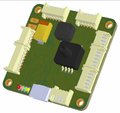
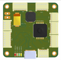
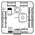
NavGo v3 3D bottom view
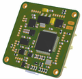
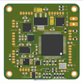
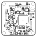
NavGo v3 3D top view
- NavGo v3 top side.png
NavGo v3 top side
- NavGo v3 bottom side.png
NavGo v3 bottom side

Pinout
Pins Name and Type are specified with respect to the Autopilot Board

Schematic

Example of Airborne Equipment Electrical Connections
PCB
Gerber & Drill Files
PCB design Eurocircuits 6-C class compliant:
Download NavGo v3 gerber & drill files (zip)
RS274X, units = Inches, format = 2:5
- NavGo_v3_SILKSCREEN_TOP.GBR (Top Component Print Layer)
- NavGo_v3_SOLDERMASK_TOP.GBR (Top Solder Mask)
- NavGo_v3_SIGNAL_TOP.GBR (Top Copper Layer)
- NavGo_v3_INTERNAL_PLANE_1.GBR (Internal Copper Layer GND)
- NavGo_v3_INTERNAL_PLANE_2.GBR (Internal Copper Layer +3.3V)
- NavGo_v3_SIGNAL_BOTTOM.GBR (Bottom Copper Layer)
- NavGo_v3_SOLDERMASK_BOTTOM.GBR (Bottom Solder Mask)
- NavGo_v3_OUTLINE.GBR (Board Outline)
- NavGo_v3_DRILL.GBR (NC XY coordinates & Drill tools sizes)
Assembly
Components Layout
NavGo v3 bottom components Layout
NavGo v3 top components Layout
NavGo v3 bottom components detail
NavGo v3 top components detail


Bill Of Material
Download NavGo v3 Bill of Material (zipped .xls file)
PCB and assembled boards suppliers
Check availability on Get Hardware page
Mechanical Dimensions

Paparazzi USB Bootloader Upload
Required components
- 1 x FTDI TTL-232R-3V3 (Digikey #768-1015-ND) USB to UART converter cable with +3.3V TTL level UART signals. (see Note 1)
- 2 x 4-pin connector housing Molex Picoblade 51021-0400 (Digikey #WM1722-ND)
- 5 x crimp terminal female Molex Picoblade 50058-8000 (Digikey #WM1775CT-ND)
- 1 x 6-pin 0.1" pitch single in line male connector header Samtec TSW-132-07-TS (Digikey #SAM1035-32-ND) or equivalent
- 28-32AWG wiring cable
- Note1: It is advised to use FTDI USB-serial converter, as serial FTDI chips are by default working well in Linux.
- The Paparazzi ground station software is configured to look for modems on FTDI ports by default.
- This harness can also serve as a modem interface (after it's use in Bootloader uploading) if you plug it on Umarim's UART1 connector
Connection Diagram
Make up a wiring harness similar to the following

Boot Sequence
