Difference between revisions of "Lisa/M v1.0"
(Added pinout details, not finished, work in progress!!!) |
|||
| (20 intermediate revisions by 7 users not shown) | |||
| Line 1: | Line 1: | ||
<div style="float: right; width: 15%"><categorytree style="float:right; clear:right; margin-left:1ex; border: 1px solid gray; padding: 0.7ex;" mode=pages>Autopilots</categorytree></div> | <div style="float: right; width: 15%"><categorytree style="float:right; clear:right; margin-left:1ex; border: 1px solid gray; padding: 0.7ex;" mode=pages>Autopilots</categorytree></div> | ||
'''[[Lisa/M_v20|THE LISA/M v2.0 IS NOW AVAILABLE]]''' | |||
<div style="float: right; width: 45%; overflow: hidden">[[Image:Lisa_M_V1_0_top_with_coin.jpg|right|600px|Lisa/M V1.0 top view]]</div> | <div style="float: right; width: 45%; overflow: hidden">[[Image:Lisa_M_V1_0_top_with_coin.jpg|right|600px|Lisa/M V1.0 top view]]</div> | ||
<div style="float: right; width: 40%">__TOC__</div> | <div style="float: right; width: 40%">__TOC__</div> | ||
'''NOTE: THERE IS A [[Lisa/M_v20|NEW VERSION OF LISA/M AVAILABLE]]''' | |||
Lisa/M is a small, general purpose autopilot designed with flexibility across multiple applications in mind. Small weight and size, with (optional) integrated [[AspirinIMU | Aspirin IMU]] and full size 0.1" servo headers make the Lisa/M suitable for both fixed-wing and rotorcraft vehicles. This autopilot is based on the STM32 for improved peripherals and faster processing. | Lisa/M is a small, general purpose autopilot designed with flexibility across multiple applications in mind. Small weight and size, with (optional) integrated [[AspirinIMU | Aspirin IMU]] and full size 0.1" servo headers make the Lisa/M suitable for both fixed-wing and rotorcraft vehicles. This autopilot is based on the STM32 for improved peripherals and faster processing. | ||
A number of tutorials are being prepared for getting started with Lisa/M: | |||
* [[Lisa/M/Tutorial/FixedWing|Fixedwing tutorial]] | |||
* [[Lisa/M/Tutorial/RotorCraft|Rotorcraft tutorial]] | |||
== Hardware Revision History == | == Hardware Revision History == | ||
| Line 10: | Line 17: | ||
!''Version #''!!''Release Date''!!''Release Notes'' | !''Version #''!!''Release Date''!!''Release Notes'' | ||
|- | |- | ||
|v1.0|| | |v1.0||MM/YYYY||Lisa/M Initial Production Release | ||
|- | |- | ||
|v0.1|| | |v0.1||MM/YYYY||Initial prototype of Lisa/M | ||
|} | |} | ||
For detailed hardware revision history, please [[Lisa/M#Detailed_Hardware_Revision_History | see below]]. | For detailed hardware revision history, please [[Lisa/M#Detailed_Hardware_Revision_History | see below]]. | ||
== Features == | == Features == | ||
Lisa/M is based on the 64 pins STM32F105RCT6 [http://www.st.com/internet/mcu/product/221023.jsp connectivity line family] processor featuring 64k of RAM and 256k of FLASH. All the pins are exposed, providing access to the complete set of the STM32 peripherals. | |||
NOTE: This MCU is different from LISA/L. Lisa/L is based on the 64 pins STM32F103RE processor featuring 64k of RAM and 512k of FLASH, which is part of the [http://www.st.com/internet/mcu/product/164485.jsp high-density performance line family]. | |||
* STM32 microcontroller [http://www.st.com/internet/com/TECHNICAL_RESOURCES/TECHNICAL_LITERATURE/DATASHEET/CD00220364.pdf STM32F105RCT6 datasheet] with 256kB flash and 64kB RAM | * STM32 microcontroller [http://www.st.com/internet/com/TECHNICAL_RESOURCES/TECHNICAL_LITERATURE/DATASHEET/CD00220364.pdf STM32F105RCT6 datasheet] with 256kB flash and 64kB RAM | ||
| Line 34: | Line 44: | ||
* 4 layers PCB design | * 4 layers PCB design | ||
with mounted IMU has the following additional sensors on board: | with mounted Aspirin IMU has the following additional sensors on board: | ||
* 3 Axis Gyroscope | * 3 Axis Gyroscope | ||
| Line 40: | Line 50: | ||
* 3 Axis Magnetometer | * 3 Axis Magnetometer | ||
The pressure sensor is mounted directly on the board as this sensor is not provided by Aspirin (''v0.1 - v1.1''). | The pressure sensor is mounted directly on the board as this sensor is not provided by Aspirin (''v0.1 - v1.1''). | ||
In short, you only need to add a high quality GPS module and then you have all necessary sensors for full attitude and altitude stabilization in an extremely small package. | |||
<gallery widths=200px heigths=200px> | <gallery widths=200px heigths=200px> | ||
| Line 50: | Line 62: | ||
== Pinout == | == Pinout == | ||
Pins Name and Type are specified with respect to the Autopilot Board | Pins Name and Type are specified with respect to the Autopilot Board. | ||
[[Image:LisaM_V1_0_top_labeled.png|900px]] | [[Image:LisaM_V1_0_top_labeled.png|900px]] | ||
| Line 60: | Line 72: | ||
|1||SERVOx||OUT||Servo signal (PWM)||style="background:Yellow; color:black"|Yellow | |1||SERVOx||OUT||Servo signal (PWM)||style="background:Yellow; color:black"|Yellow | ||
|- | |- | ||
|2|| SV||PWR||Servo Voltage Rail||style="background:red; color:white"|Red | |2||SV||PWR||Servo Bus Voltage Rail (conf w/ JP1)||style="background:red; color:white"|Red | ||
|- | |- | ||
|3||GND||PWR||common ground||style="background:black; color:white"|Black | |3||GND||PWR||common ground||style="background:black; color:white"|Black | ||
| Line 80: | Line 92: | ||
|1||GND||PWR||common ground||style="background:black; color:white"|Black | |1||GND||PWR||common ground||style="background:black; color:white"|Black | ||
|- | |- | ||
|2|| | |2|| +3V3||PWR||UART Voltage (conf w/ JP6 and JP7)||style="background:Red; color:white"|Red | ||
|- | |- | ||
|3||TX||OUT||USART1 Serial Output (3.3V level)||style="background:Yellow; color:black"|Yellow | |3||TX||OUT||USART1 Serial Output (3.3V level)||style="background:Yellow; color:black"|Yellow | ||
|- | |- | ||
|4||RX||IN||USART1 Serial Input (3.3V level | |4||RX||IN||USART1 Serial Input (3.3V level)(5V tolerant)||style="background:Orange; color:white"|Orange | ||
|} | |} | ||
| Line 96: | Line 108: | ||
|2|| +3V3||PWR||3.3V Rail from autopilot||style="background:Red; color:white"|Red | |2|| +3V3||PWR||3.3V Rail from autopilot||style="background:Red; color:white"|Red | ||
|- | |- | ||
|3||RX3||IN||USART3 Serial Input (3.3V level)||style="background:Orange; color:white"|Orange | |3||RX3||IN||USART3 Serial Input (3.3V level)(5V tolerant)||style="background:Orange; color:white"|Orange | ||
|- | |- | ||
|4||GND||PWR||common ground||style="background:black; color:white"|Black | |4||GND||PWR||common ground||style="background:black; color:white"|Black | ||
| Line 102: | Line 114: | ||
|5|| +3V3||PWR||3.3V Rail from autopilot||style="background:Red; color:white"|Red | |5|| +3V3||PWR||3.3V Rail from autopilot||style="background:Red; color:white"|Red | ||
|- | |- | ||
|6||RX5||IN|| | |6||RX5||IN||UART5 Serial Input (3.3V level)(5V tolerant)||style="background:Orange; color:white"|Orange | ||
|} | |} | ||
| Line 114: | Line 126: | ||
|2|| +3V3||PWR||3.3V Rail from autopilot||style="background:Red; color:white"|Red | |2|| +3V3||PWR||3.3V Rail from autopilot||style="background:Red; color:white"|Red | ||
|- | |- | ||
|3||PC10||I/O||GPIO PC10||style="background:#FFA1B2; color:black"|Pink | |3||PC10||I/O||GPIO PC10 = LED 5 ||style="background:#FFA1B2; color:black"|Pink | ||
|- | |- | ||
|4||PC12||I/O||GPIO PC12||style="background:#FDC579; color:black"|Dark Tan | |4||PC12||I/O||GPIO PC12 = LED 4 ||style="background:#FDC579; color:black"|Dark Tan | ||
|- | |- | ||
|5||TRST||I/O||JTAG_TRST||style="background:#FED6B1; color:black"|Light Tan | |5||TRST||I/O||JTAG_TRST = LED1 ||style="background:#FED6B1; color:black"|Light Tan | ||
|} | |} | ||
| Line 154: | Line 166: | ||
|1||GND||PWR||common ground||style="background:black; color:white"|Black | |1||GND||PWR||common ground||style="background:black; color:white"|Black | ||
|- | |- | ||
|2|| V_BATT||PWR|| | |2|| V_BATT||PWR||V_BAT Bus on autopilot, voltage divider for V_BAT_MEAS, (conf w/ JP2 to connect to V_IN)||style="background:Red; color:white"|Red | ||
|- | |- | ||
|3|| V_IN||PWR|| | |3|| V_IN||PWR||Connected to autopilot voltage regulator inputs (conf w/ JP1, JP2 and JP3)||style="background:Red; color:white"|Red | ||
|- | |- | ||
|4||CANL||I/O||CANL||style="background:orange; color:white"|Orange | |4||CANL||I/O||CANL (5V level)||style="background:orange; color:white"|Orange | ||
|- | |- | ||
|5||CANH||I/O||CANH||style="background:yellow; color:black"|Yellow | |5||CANH||I/O||CANH (5V level)||style="background:yellow; color:black"|Yellow | ||
|- | |- | ||
|6||SCL||I/O||SCL||style="background:green; color:white"|Green | |6||SCL||I/O||SCL (5V level)||style="background:green; color:white"|Green | ||
|- | |- | ||
|7||SDA||I/O||SDA||style="background:blue; color:white"|Blue | |7||SDA||I/O||SDA (5V level)||style="background:blue; color:white"|Blue | ||
|} | |} | ||
| Line 198: | Line 210: | ||
|3|| +5V||PWR||5V Rail from autopilot||style="background:Red; color:white"|Red | |3|| +5V||PWR||5V Rail from autopilot||style="background:Red; color:white"|Red | ||
|- | |- | ||
|4||ADC1||In|| | |4||ADC1||In||ADC1||style="background:green; color:white"|Green | ||
|- | |- | ||
|5||ADC2||In|| | |5||ADC2||In||ADC2||style="background:blue; color:white"|Blue | ||
|- | |- | ||
|6||ADC3||In|| | |6||ADC3||In||ADC3||style="background:#FED6B1; color:black"|Light Tan | ||
|} | |} | ||
| Line 212: | Line 224: | ||
|1||GND||PWR||common ground||style="background:black; color:white"|Black | |1||GND||PWR||common ground||style="background:black; color:white"|Black | ||
|- | |- | ||
|2||VCC||PWR||UART Voltage||style="background:Red; color:white"|Red | |2||VCC||PWR||UART Voltage (conf w/ JP4 and JP5)||style="background:Red; color:white"|Red | ||
|- | |- | ||
|3||TX||OUT||USART2 Serial Output (3.3V level)||style="background:Yellow; color:black"|Yellow | |3||TX||OUT||USART2 Serial Output (3.3V level)||style="background:Yellow; color:black"|Yellow | ||
|- | |- | ||
|4||RX||IN||USART2 Serial Input (3.3V level | |4||RX||IN||USART2 Serial Input (3.3V level)('''NOT 5V TOLERANT''')||style="background:Orange; color:white"|Orange | ||
|} | |} | ||
| Line 228: | Line 240: | ||
|2|| +3V3||PWR||3.3V Rail from autopilot||style="background:Red; color:white"|Red | |2|| +3V3||PWR||3.3V Rail from autopilot||style="background:Red; color:white"|Red | ||
|- | |- | ||
|3||SCL||I/O||SCL||style="background:green; color:white"|Green | |3||SCL||I/O||SCL (3.3V level)||style="background:green; color:white"|Green | ||
|- | |- | ||
|4||SDA||I/O||SDA||style="background:blue; color:white"|Blue | |4||SDA||I/O||SDA (3.3V level)||style="background:blue; color:white"|Blue | ||
|} | |} | ||
=== Jumper Configuration === | |||
There are a number of jumpers on Lisa/M used to configure voltage levels and power input. | |||
<gallery widths=380px heights=205px> | |||
Image:LisaM_V1_0_top_jumpers_and_leds.png | Lisa/M v1.0 Top Jumpers and LEDs | |||
Image:LisaM_V1_0_bottom_jumpers.png | Lisa/M v1.0 Bottom Jumpers | |||
</gallery> | |||
<br style="clear:both"> | |||
{|border="1" cellspacing="0" style="text-align:center" cellpadding="2%" width="70%" | |||
|+'''Power Jumper Configuration''' | |||
!width="7%"|''Jumper''!!width="20%"|''Bus Connection''!!width="7%"|''Default''!!''Description'' | |||
|- | |||
|JP1||SERVO_BUS to V_IN||style="background:black; color:white"|CLOSED||Connects servo header voltage rail SERVO_BUS to autopilot input voltage V_IN rail | |||
|- | |||
|JP2||V_BAT to V_IN||OPEN||Connects I2C1/CAN rail V_BAT to autopilot input voltage V_IN rail | |||
|- | |||
|JP3||V_IN to +5V||OPEN||Connects autopilot input voltage V_IN rail to autopilot +5V rail, bypassing onboard 5V supply | |||
|} | |||
{|border="1" cellspacing="0" style="text-align:center" cellpadding="2%" width="70%" | |||
|+'''UART1 VCC Configuration''' | |||
!width="7%"|''Jumper''!!width="20%"|''Bus Connection''!!width="7%"|''Default''!!''Description'' | |||
|- | |||
|JP6||UART1_VCC to V_IN||OPEN||Connects UART1 connector VCC to autopilot input voltage V_IN rail | |||
|- | |||
|JP7||UART1_VCC to +3V3||style="background:black; color:white"|CLOSED||Connects UART1 connector VCC to autopilot +3V3 rail | |||
|} | |||
'''WARNING: DO NOT CLOSE BOTH JP6 AND JP7 SIMULTANEOUSLY!!!''' | |||
{|border="1" cellspacing="0" style="text-align:center" cellpadding="2%" width="70%" | |||
|+'''UART2 VCC Configuration''' | |||
!width="7%"|''Jumper''!!width="20%"|''Bus Connection''!!width="7%"|''Default''!!''Description'' | |||
|- | |||
|JP4||UART2_VCC to V_IN||OPEN||Connects UART2 connector VCC to autopilot input voltage V_IN rail '''SEE WARNING BELOW''' | |||
|- | |||
|JP5||UART2_VCC to +3V3||style="background:black; color:white"|CLOSED||Connects UART2 connector VCC to autopilot +3V3 rail | |||
|} | |||
'''WARNING: UART2 RX is NOT 5V TOLERANT. Thus, while possible to connect UART2_VCC to V_IN, DO NOT ATTEMPT THIS. Only use JP5 (the default). | |||
'''WARNING: DO NOT CLOSE BOTH JP4 AND JP5 SIMULTANEOUSLY!!!''' | |||
=== Powering the Board === | |||
The 3.3V regulator on Lisa/M is a [http://www.micrel.com/page.do?page=/product-info/products/mic5209.shtml MIC5209-3.3YM] capable of delivering up to 500mA. While it is possible to power this regulator with up to 16V, experience has shown that this regulator can become very hot in operation with high input voltages, resulting in potential thermal shutdown while in flight. Depending on the expected current draw, it is best to power this regulator with a lower voltage. 5V is the perfect choice. | |||
The onboard 5V regulator on Lisa/M is a [http://www.national.com/pf/LP/LP2992.html LP2992], a low-noise, low-dropout linear regulator capable of delivering up to 250mA. This regulator can be bypassed with JP3, connecting the autopilot V_IN bus directly to the autopilot 5V bus if, for example, one is using an external 5V regulated supply. | |||
== Schematic == | == Schematic == | ||
| Line 250: | Line 313: | ||
Need an Umarim V1.0-style ([[Umarim_v10#Large_Aircraft_Connection_Diagram | here]]) large aircraft airborne equipment electrical connections diagram here. | Need an Umarim V1.0-style ([[Umarim_v10#Large_Aircraft_Connection_Diagram | here]]) large aircraft airborne equipment electrical connections diagram here. | ||
<br style="clear:both"> | <br style="clear:both"> | ||
=== R/C Receivers === | |||
There is Spektrum parser available already, enabling the direct use of 1 or 2 Spektrum satellite receivers. | |||
[[Image:Lisa_M_V1_0_satellite_receiver_connection_labeled.png|500px|Connection of Spektrum Satellite Receivers to Lisa/M v1.0]] | |||
Also UART pins can be used as general purpose I/O to be used for PPM input. Additionally [[PPM_Encoder | PPM encoder]] can be used to avoid receiver hardware modification. | |||
== PCB == | == PCB == | ||
| Line 267: | Line 338: | ||
=== Bill Of Material === | === Bill Of Material === | ||
'''''Download | '''''Download Lisa/M v1.0 Bill Of Material (zipped .xls file)''''' ''NOT YET AVAILABLE BUT SEE [[Lisa/M#Downloads|Downloads]]'' | ||
<br> | <br> | ||
<br> | <br> | ||
| Line 283: | Line 354: | ||
'''Source files''' | '''Source files''' | ||
:*download available on GitHub: ''[https://github.com/paparazzi/paparazzi-hardware/tree/master/controller/lisa_m/v1.0 Lisa/M v1.0 Cadsoft Eagle | :*download available on GitHub: ''[https://github.com/paparazzi/paparazzi-hardware/tree/master/controller/lisa_m/v1.0 Lisa/M v1.0 Cadsoft Eagle 5.x Design]'' | ||
'''Gerber & Drill files''' | '''Gerber & Drill files''' | ||
:*download ''NOT YET AVAILABLE'' Need generated gerbers and drill files | :*download ''NOT YET AVAILABLE'' Need generated gerbers and drill files | ||
| Line 290: | Line 361: | ||
:*download ''NOT YET AVAILABLE'' Need Lisa/M v1.0 Bill Of Material | :*download ''NOT YET AVAILABLE'' Need Lisa/M v1.0 Bill Of Material | ||
== | == Upload firmware == | ||
Uploading firmware onboard USB is not possible with this boart. The boords need hardware modification to make it possible. A very nice way to upload, a.k.a. flashing new Paparazzi code to the board is to use a [[Lisa/M#JTAG|JTAG]] adapter. Less convenient since it takes a special adapter. But this adapter makes it more convenient when testing; one does not need to repower the board to reflash. And flashing via JTag cable is very fast. Also debugging the autopilot is very handy with JTAG. | |||
=== Required components === | === Required components === | ||
| Line 301: | Line 372: | ||
=== Boot Sequence === | === Boot Sequence === | ||
== JTAG == | |||
JTAG can be used to upload firmware if no bootloader as present. It can also be used for debugging. | |||
* [[JTAG]] description; | |||
* General [[Dev/Debugging|debugging information]]; | |||
* [[DevGuide/JTAG-Debug|JTAG usage]], includes Eclipse uplink tutorial. | |||
== Detailed Hardware Revision History == | == Detailed Hardware Revision History == | ||
=== Changes Between v1. | === Changes Between v1.0 and v1.1 === | ||
* Removed pull-ups on the USB gpio | * Removed pull-ups on the USB gpio | ||
* Removed pull-ups on the CAN gpio | * Removed pull-ups on the CAN gpio | ||
| Line 333: | Line 404: | ||
=== Changes Between v0.1 and v1.0 === | === Changes Between v0.1 and v1.0 === | ||
* Switched to stm32f105 to be able to use usb and can at the same time | * Switched to stm32f105 to be able to use usb and can at the same time | ||
* Added alternative use of the adc lines as led output | * Added alternative use of the adc lines as led output | ||
| Line 338: | Line 410: | ||
=== Hardware Change Requests === | === Hardware Change Requests === | ||
* REQ: Replace BMP085 with MS5611 (the MS5611 seems to be better in performance then the BMP but it is more expensive and seems to be more difficult to obtain. | * REQ: Replace BMP085 with MS5611 (the MS5611 seems to be better in performance then the BMP but it is more expensive and seems to be more difficult to obtain. | ||
** A: This upgrade will be available through Aspirin v2.0 --[[User:Esden|Esden]] 22:54, 5 January 2012 (CET) | ** A: This upgrade will be available through Aspirin v2.0 --[[User:Esden|Esden]] 22:54, 5 January 2012 (CET) | ||
| Line 465: | Line 418: | ||
* REQ: Separate spot for external power if powered via separate battery. Realizing we can via Servo ports by Bridge J1 but still like to measure board voltage then and have a way to add power without mistakenly inject CAN Molex into SPI. | * REQ: Separate spot for external power if powered via separate battery. Realizing we can via Servo ports by Bridge J1 but still like to measure board voltage then and have a way to add power without mistakenly inject CAN Molex into SPI. | ||
== | === USB usage Notes for v1.0 === | ||
Lisa/M v1.0's USB circuit is not working out of the box. If you wish to use it for example in the combination with Luftboot you will need to make some slight hardware modifications to the board. | |||
== | |||
* You need to remove pull-up resistors on USB_DM and USB_DP lines (R27 and R28) | |||
* While using the USB interface you need to have UART1_TX connected to 3v3 or USB_VBUS (This means you can not transfer data to the GPS while using USB) | |||
* Optionally you can also remove R14 and Q2 | |||
The GPS UART (UART1) and USB collision was fixed as of Lisa/M v2.0 where the usage of UART1 was swapped with UART3. | |||
To use Luftboot on Lisa/M 1.0 then follow instructions for [[Luftboot]] after these hardware modifications. | |||
[[Category:Lisa]] [[Category:User_Documentation]] | [[Category:Lisa]] [[Category:User_Documentation]] [[Category:Autopilots]] | ||
Latest revision as of 19:15, 2 August 2013
THE LISA/M v2.0 IS NOW AVAILABLE

NOTE: THERE IS A NEW VERSION OF LISA/M AVAILABLE
Lisa/M is a small, general purpose autopilot designed with flexibility across multiple applications in mind. Small weight and size, with (optional) integrated Aspirin IMU and full size 0.1" servo headers make the Lisa/M suitable for both fixed-wing and rotorcraft vehicles. This autopilot is based on the STM32 for improved peripherals and faster processing.
A number of tutorials are being prepared for getting started with Lisa/M:
Hardware Revision History
| Version # | Release Date | Release Notes |
|---|---|---|
| v1.0 | MM/YYYY | Lisa/M Initial Production Release |
| v0.1 | MM/YYYY | Initial prototype of Lisa/M |
For detailed hardware revision history, please see below.
Features
Lisa/M is based on the 64 pins STM32F105RCT6 connectivity line family processor featuring 64k of RAM and 256k of FLASH. All the pins are exposed, providing access to the complete set of the STM32 peripherals. NOTE: This MCU is different from LISA/L. Lisa/L is based on the 64 pins STM32F103RE processor featuring 64k of RAM and 512k of FLASH, which is part of the high-density performance line family.
- STM32 microcontroller STM32F105RCT6 datasheet with 256kB flash and 64kB RAM
- Pressure sensor BMP085
- 7 x Analog input channels
- 3 x Generic digital in-/out-puts
- 2 x 3.3V TTL UART (5V tolerant)
- 7 x Servo PPM outputs
- 1 x CAN bus
- 1 x SPI bus
- 1 x I2C bus
- 1 x Micro USB
- 4 x status LEDs with attached test point
- 10.8 grams (0.4 oz) (with Aspirin IMU mounted)
- 9.9 grams (0.35 oz) (without Aspirin IMU mounted)
- ~33mm x ~56mm x ~10mm
- 4 layers PCB design
with mounted Aspirin IMU has the following additional sensors on board:
- 3 Axis Gyroscope
- 3 Axis Accelerometer
- 3 Axis Magnetometer
The pressure sensor is mounted directly on the board as this sensor is not provided by Aspirin (v0.1 - v1.1).
In short, you only need to add a high quality GPS module and then you have all necessary sensors for full attitude and altitude stabilization in an extremely small package.
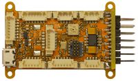
Lisa/M V1.0 top view
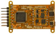
Lisa/M V1.0 bottom view
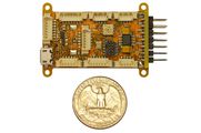
Lisa/M V1.0 top view
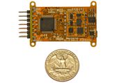
Lisa/M V1.0 bottom view


Pinout
Pins Name and Type are specified with respect to the Autopilot Board.

| Pin # | Name | Type | Description | Color |
|---|---|---|---|---|
| 1 | SERVOx | OUT | Servo signal (PWM) | Yellow |
| 2 | SV | PWR | Servo Bus Voltage Rail (conf w/ JP1) | Red |
| 3 | GND | PWR | common ground | Black |
| Pin # | Name | Type | Description | Color |
|---|---|---|---|---|
| 1 | N/A | N/A | JTAG Debug Header | None |
| Pin # | Name | Type | Description | Color |
|---|---|---|---|---|
| 1 | GND | PWR | common ground | Black |
| 2 | +3V3 | PWR | UART Voltage (conf w/ JP6 and JP7) | Red |
| 3 | TX | OUT | USART1 Serial Output (3.3V level) | Yellow |
| 4 | RX | IN | USART1 Serial Input (3.3V level)(5V tolerant) | Orange |
| Pin # | Name | Type | Description | Color |
|---|---|---|---|---|
| 1 | GND | PWR | common ground | Black |
| 2 | +3V3 | PWR | 3.3V Rail from autopilot | Red |
| 3 | RX3 | IN | USART3 Serial Input (3.3V level)(5V tolerant) | Orange |
| 4 | GND | PWR | common ground | Black |
| 5 | +3V3 | PWR | 3.3V Rail from autopilot | Red |
| 6 | RX5 | IN | UART5 Serial Input (3.3V level)(5V tolerant) | Orange |
| Pin # | Name | Type | Description | Color |
|---|---|---|---|---|
| 1 | GND | PWR | common ground | Black |
| 2 | +3V3 | PWR | 3.3V Rail from autopilot | Red |
| 3 | PC10 | I/O | GPIO PC10 = LED 5 | Pink |
| 4 | PC12 | I/O | GPIO PC12 = LED 4 | Dark Tan |
| 5 | TRST | I/O | JTAG_TRST = LED1 | Light Tan |
| Pin # | Name | Type | Description | Color |
|---|---|---|---|---|
| 1 | GND | PWR | common ground | Black |
| 2 | +3V3 | PWR | 3.3V Rail from autopilot | Red |
| 3 | +5V | PWR | 5V Rail from autopilot | Red |
| 4 | ADC4 | I/O | ADC4 | Magenta |
| 5 | ADC6 | I/O | ADC6 | Pink |
| 6 | BOOT | I/O | BOOT | Grey |
| Pin # | Name | Type | Description | Color |
|---|---|---|---|---|
| 1 | N/A | N/A | USB | None |
| Pin # | Name | Type | Description | Color |
|---|---|---|---|---|
| 1 | GND | PWR | common ground | Black |
| 2 | V_BATT | PWR | V_BAT Bus on autopilot, voltage divider for V_BAT_MEAS, (conf w/ JP2 to connect to V_IN) | Red |
| 3 | V_IN | PWR | Connected to autopilot voltage regulator inputs (conf w/ JP1, JP2 and JP3) | Red |
| 4 | CANL | I/O | CANL (5V level) | Orange |
| 5 | CANH | I/O | CANH (5V level) | Yellow |
| 6 | SCL | I/O | SCL (5V level) | Green |
| 7 | SDA | I/O | SDA (5V level) | Blue |
| Pin # | Name | Type | Description | Color |
|---|---|---|---|---|
| 1 | GND | PWR | common ground | Black |
| 2 | +3V3 | PWR | 3.3V Rail from autopilot | Red |
| 3 | MOSI | Out | MOSI | Orange |
| 4 | MISO | In | MISO | Yellow |
| 5 | SCK | Out | SCK | Green |
| 6 | SS | Out | SS | Blue |
| 7 | DRDY | I/O | DRDY | Dark Tan |
| Pin # | Name | Type | Description | Color |
|---|---|---|---|---|
| 1 | GND | PWR | common ground | Black |
| 2 | +3V3 | PWR | 3.3V Rail from autopilot | Red |
| 3 | +5V | PWR | 5V Rail from autopilot | Red |
| 4 | ADC1 | In | ADC1 | Green |
| 5 | ADC2 | In | ADC2 | Blue |
| 6 | ADC3 | In | ADC3 | Light Tan |
| Pin # | Name | Type | Description | Color |
|---|---|---|---|---|
| 1 | GND | PWR | common ground | Black |
| 2 | VCC | PWR | UART Voltage (conf w/ JP4 and JP5) | Red |
| 3 | TX | OUT | USART2 Serial Output (3.3V level) | Yellow |
| 4 | RX | IN | USART2 Serial Input (3.3V level)(NOT 5V TOLERANT) | Orange |
| Pin # | Name | Type | Description | Color |
|---|---|---|---|---|
| 1 | GND | PWR | common ground | Black |
| 2 | +3V3 | PWR | 3.3V Rail from autopilot | Red |
| 3 | SCL | I/O | SCL (3.3V level) | Green |
| 4 | SDA | I/O | SDA (3.3V level) | Blue |
Jumper Configuration
There are a number of jumpers on Lisa/M used to configure voltage levels and power input.
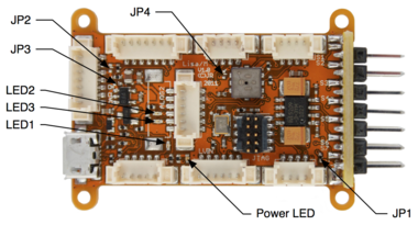
Lisa/M v1.0 Top Jumpers and LEDs
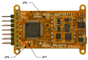
Lisa/M v1.0 Bottom Jumpers


| Jumper | Bus Connection | Default | Description |
|---|---|---|---|
| JP1 | SERVO_BUS to V_IN | CLOSED | Connects servo header voltage rail SERVO_BUS to autopilot input voltage V_IN rail |
| JP2 | V_BAT to V_IN | OPEN | Connects I2C1/CAN rail V_BAT to autopilot input voltage V_IN rail |
| JP3 | V_IN to +5V | OPEN | Connects autopilot input voltage V_IN rail to autopilot +5V rail, bypassing onboard 5V supply |
| Jumper | Bus Connection | Default | Description |
|---|---|---|---|
| JP6 | UART1_VCC to V_IN | OPEN | Connects UART1 connector VCC to autopilot input voltage V_IN rail |
| JP7 | UART1_VCC to +3V3 | CLOSED | Connects UART1 connector VCC to autopilot +3V3 rail |
WARNING: DO NOT CLOSE BOTH JP6 AND JP7 SIMULTANEOUSLY!!!
| Jumper | Bus Connection | Default | Description |
|---|---|---|---|
| JP4 | UART2_VCC to V_IN | OPEN | Connects UART2 connector VCC to autopilot input voltage V_IN rail SEE WARNING BELOW |
| JP5 | UART2_VCC to +3V3 | CLOSED | Connects UART2 connector VCC to autopilot +3V3 rail |
WARNING: UART2 RX is NOT 5V TOLERANT. Thus, while possible to connect UART2_VCC to V_IN, DO NOT ATTEMPT THIS. Only use JP5 (the default).
WARNING: DO NOT CLOSE BOTH JP4 AND JP5 SIMULTANEOUSLY!!!
Powering the Board
The 3.3V regulator on Lisa/M is a MIC5209-3.3YM capable of delivering up to 500mA. While it is possible to power this regulator with up to 16V, experience has shown that this regulator can become very hot in operation with high input voltages, resulting in potential thermal shutdown while in flight. Depending on the expected current draw, it is best to power this regulator with a lower voltage. 5V is the perfect choice.
The onboard 5V regulator on Lisa/M is a LP2992, a low-noise, low-dropout linear regulator capable of delivering up to 250mA. This regulator can be bypassed with JP3, connecting the autopilot V_IN bus directly to the autopilot 5V bus if, for example, one is using an external 5V regulated supply.
Schematic
LisaM V1.0 Schematic Sheet 1/3
LisaM V1.0 Schematic Sheet 2/3
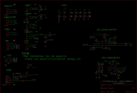
LisaM V1.0 Schematic Sheet 3/3


Examples of Airborne Equipment Electrical Connections
Small Aircraft Connection Diagram
Need an Umarim_v1.0-style ( here) small aircraft airborne equipment electrical connections here.
Large Aircraft Connection Diagram
Need an Umarim V1.0-style ( here) large aircraft airborne equipment electrical connections diagram here.
R/C Receivers
There is Spektrum parser available already, enabling the direct use of 1 or 2 Spektrum satellite receivers.

Also UART pins can be used as general purpose I/O to be used for PPM input. Additionally PPM encoder can be used to avoid receiver hardware modification.
PCB
Gerber & Drill Files
Download Lisa/M v1.0 gerber & drill files (zip) NOT YET AVAILABLE BUT SEE Downloads Need some generated gerbers and drill files here.
Assembly
Components Layout
NOT YET AVAILABLE BUT SEE Downloads Need some top and bottom of board images and line drawings here.
Bill Of Material
Download Lisa/M v1.0 Bill Of Material (zipped .xls file) NOT YET AVAILABLE BUT SEE Downloads
PCB and assembled boards suppliers
Available on Get Hardware page, hopefully :)
Mechanical Dimensions

Downloads
Source files
- download available on GitHub: Lisa/M v1.0 Cadsoft Eagle 5.x Design
Gerber & Drill files
- download NOT YET AVAILABLE Need generated gerbers and drill files
Assembly files
- download NOT YET AVAILABLE Need Lisa/M v1.0 Components layouts (pdf)
- download NOT YET AVAILABLE Need Lisa/M v1.0 Bill Of Material
Upload firmware
Uploading firmware onboard USB is not possible with this boart. The boords need hardware modification to make it possible. A very nice way to upload, a.k.a. flashing new Paparazzi code to the board is to use a JTAG adapter. Less convenient since it takes a special adapter. But this adapter makes it more convenient when testing; one does not need to repower the board to reflash. And flashing via JTag cable is very fast. Also debugging the autopilot is very handy with JTAG.
Required components
Connection Diagram
Boot Sequence
JTAG
JTAG can be used to upload firmware if no bootloader as present. It can also be used for debugging.
- JTAG description;
- General debugging information;
- JTAG usage, includes Eclipse uplink tutorial.
Detailed Hardware Revision History
Changes Between v1.0 and v1.1
- Removed pull-ups on the USB gpio
- Removed pull-ups on the CAN gpio
- Connected usb_vbus to pa9 (needed by the USBotg)
- Removed USB pullup transistor as usbotg has a built in pullup
- Swapped UART1 with UART3 (uart1 was used for gps and pa9 was it's tx line, to be able to talk to the gps unit uart3 is a better choice, as uart1 only has an rx line now it is a better choice for spektrum RX modules)
- Removed USART3 TX gpio from the GPIO connector and moved to the GPS connector
- Added voltage selector jumpers to the RC RX connector; to enable powering of 3v3 or an 5v receivers
- Replaced vertical board solution with through hole servo pin headers (easier assembly)
- Servo connectors are in groups of two; for easier assembly
- Servo VBUS is connected together on all four layers; for lower resistance
- Moved LED's from under the analog2 connector; to be able to populate LED's and the connector
- Moved the RC RX connector a bit; to prevent crashing with the jtag plug
- Added one additional servo connector; now we have all 8 accessible through the standard servo connectors
- Fixed servo channel labeling to start at S0 as it is the case on TWOG and Tiny autopilot boards
- Added secondary through hole picoblade USB connector for easier routing of USB inside an airframe
- ...
Changes Between v0.1 and v1.0
- Switched to stm32f105 to be able to use usb and can at the same time
- Added alternative use of the adc lines as led output
- ...
Hardware Change Requests
- REQ: Replace BMP085 with MS5611 (the MS5611 seems to be better in performance then the BMP but it is more expensive and seems to be more difficult to obtain.
- A: This upgrade will be available through Aspirin v2.0 --Esden 22:54, 5 January 2012 (CET)
- REQ: Replace 7 Pin CAN with molex with something less risky to be inserted in 7 Pin SPI in relation to powering the board via CAN molex.
- REQ: Separate spot for external power if powered via separate battery. Realizing we can via Servo ports by Bridge J1 but still like to measure board voltage then and have a way to add power without mistakenly inject CAN Molex into SPI.
USB usage Notes for v1.0
Lisa/M v1.0's USB circuit is not working out of the box. If you wish to use it for example in the combination with Luftboot you will need to make some slight hardware modifications to the board.
- You need to remove pull-up resistors on USB_DM and USB_DP lines (R27 and R28)
- While using the USB interface you need to have UART1_TX connected to 3v3 or USB_VBUS (This means you can not transfer data to the GPS while using USB)
- Optionally you can also remove R14 and Q2
The GPS UART (UART1) and USB collision was fixed as of Lisa/M v2.0 where the usage of UART1 was swapped with UART3.
To use Luftboot on Lisa/M 1.0 then follow instructions for Luftboot after these hardware modifications.