|
|
| Line 27: |
Line 27: |
| [[Image:booz2_a5.jpg|240px]] | | [[Image:booz2_a5.jpg|240px]] |
|
| |
|
| == Program Sources == | | == Running a simulator == |
|
| |
|
| Everything is at savannah.
| | Booz features a simulator which can serve many purposes, from learning how to operate it to evaluating control or estimation algorithms. |
| -hardware in paparazzi4/trunk/hw/booz
| | |
| -code in paparazzi3/trunk
| | [[BoozSimulator]] |
|
| |
|
| == Hardware == | | == Hardware == |
| Line 70: |
Line 70: |
|
| |
|
|
| |
|
| == Running a simulator ==
| |
|
| |
| [[BoozSimulator]]
| |
|
| |
|
| == Hardware Test == | | == Hardware Test == |
|
| |
|
| Booz comes with a number of simple test programs that you can use to validate a newly assembled board or learn how booz code works in case you want to extend it. | | Booz comes with a number of simple test programs that you can use to validate a newly assembled board or learn how booz code works in case you want to extend it. |
| The ''Makefile'' for those is in ''conf/autopilot/booz2_test_progs.makefile''
| |
|
| |
|
| |
| === test_downlink ===
| |
| Paparazzi's Makefile allow you to build different ''TARGETS'' (aka programs) using a doted notation. The begining of the ''Makefile'' reads
| |
|
| |
| <syntaxhighlight lang="make">
| |
| #
| |
| # test downlink
| |
| #
| |
| test_downlink.ARCHDIR = $(ARCHI)
| |
| test_downlink.ARCH = arm7tdmi
| |
| test_downlink.TARGET = test_downlink
| |
| test_downlink.TARGETDIR = test_downlink
| |
| #
| |
| test_downlink.CFLAGS += -DBOARD_CONFIG=$(BOARD_CFG) $(BOOZ_CFLAGS)
| |
| test_downlink.CFLAGS += -DPERIPHERALS_AUTO_INIT
| |
| test_downlink.srcs += $(SRC_BOOZ_TEST)/booz2_test_downlink.c
| |
| test_downlink.CFLAGS += -DUSE_LED
| |
| test_downlink.CFLAGS += -DPERIODIC_TASK_PERIOD='SYS_TICS_OF_SEC((1./10.))' -DTIME_LED=1
| |
| test_downlink.srcs += sys_time.c $(SRC_ARCH)/sys_time_hw.c $(SRC_ARCH)/armVIC.c
| |
| #
| |
| test_downlink.CFLAGS += -DUSE_UART1 -DUART1_BAUD=B57600
| |
| test_downlink.srcs += $(SRC_ARCH)/uart_hw.c
| |
| #
| |
| test_downlink.CFLAGS += -DDOWNLINK -DDOWNLINK_TRANSPORT=PprzTransport -DDOWNLINK_DEVICE=Uart1
| |
| test_downlink.srcs += downlink.c pprz_transport.c
| |
| </syntaxhighlight>
| |
|
| |
| FIXME: More on this when syntax highlighting/line numbering works
| |
|
| |
| The command line to compile the "test_downlink" target for the BOOZ2_A1 aircraft would be
| |
|
| |
| make AIRCRAFT=BOOZ2_A1 test_downlink.compile
| |
|
| |
| and to upload this program to your board ( you don't really need to type the previous command, make is smart and will compile your program if needed when you ask him to upload it )
| |
|
| |
| make AIRCRAFT=BOOZ2_A1 test_downlink.upload
| |
|
| |
|
| |
| === test_max1168 ===
| |
|
| |
| the ''max1168'' is the 16 bits analog to digital converter chip used on the IMU to sample gyros and accels.
| |
|
| |
| make AIRCRAFT=BOOZ2_A1 test_max1168.upload
| |
|
| |
|
| | more info in [[BoozHardwareTest]] |
|
| |
|
| == Sensors Calibration == | | == Sensors Calibration == |
| Line 128: |
Line 81: |
| All our sensors needs to be calibrated in order to provide useful informations. | | All our sensors needs to be calibrated in order to provide useful informations. |
|
| |
|
| Accelerometers and Magnetometers calibration is critical for AHRS performances and can be performed using no special hardware. For the magnetometer, it is even very important that the calibration be performed in the fully assembled vehicle, with all systems powered. This is the so-called hard-iron calibration and will allow us to compensate for any constant parasitic magnetic field generated by the vehicle.
| | more info in [[BoozSensorsCalibration]] |
| The calibration process consist in finding a set of neutrals and scale factors for each sensor, such as
| |
| | |
| | |
| <math>
| |
| \begin{pmatrix}physical\_value_x\\physical\_value_y\\physical\_value_z\end{pmatrix} = \begin{pmatrix}sf_x&0&0\\0&sf_y&0\\0&0&sf_z\end{pmatrix} * (\begin{pmatrix}sensor_x\\sensor_y\\sensor_z\end{pmatrix}-\begin{pmatrix}n_x\\n_y\\n_z\end{pmatrix})
| |
| </math>
| |
| | |
| | |
| The principle of the calibration is the following : An accelerometer, on a vehicle at rest measures a constant vector ( the opposite of gravity ) in the earth frame, expressed in the vehicle frame.
| |
| | |
| <math>
| |
| DCM * \begin{pmatrix}0\\0\\-9.81\end{pmatrix} =
| |
| \begin{pmatrix}sf_x&0&0\\0&sf_y&0\\0&0&sf_z\end{pmatrix} * (\begin{pmatrix}sensor_x\\sensor_y\\sensor_z\end{pmatrix}-\begin{pmatrix}n_x\\n_y\\n_z\end{pmatrix})
| |
| </math>
| |
| | |
| | |
| DCM is a rotation matrix that converts between earth frame and body frame. It will change when we change the orientation of the vehicle. Nevertheless, a rotation conserves the norm of a vector. We can thus obtain the following scalar equation that doesn't depend on the vehicle orientation :
| |
| | |
| | |
| <math>
| |
| 9.81^2 = ( sf_x(sensor_x-n_x) )^2 + (sf_y(sensor_y-n_y) )^2 + (sf_z(sensor_z-n_z) )^2
| |
| </math>
| |
| | |
| We can then record an important number of measurements in different orientations and find the set of scale factor and neutral giving the norm closest to 9.81
| |
| | |
| Booz comes with a ( very unfriendly ) scilab script to perform this operation ( sw/tools/calibration/calib_accel_mag.sce ). Here is the way to use it
| |
| | |
| Switch to the "raw sensors" telemetry mode and launch "server" to record a log.
| |
| | |
| Move the quad in different orientations ( upright, inverted, on nose, on tail, on right side, on left side ) . You can also take some measurememts banking 45 degres.
| |
| | |
| Try to get an homogeneous distribution of your measurements. I find it better to let the quad rest while measuring. You can then run the scilab script to get your calibration coefficients. It first makes an initial guess using min and max, ie for each axis
| |
| | |
| neutral = 0.5 * (max + min)
| |
| | |
| sensitivity = 0.5*(max-min)
| |
| | |
| It then uses scilab's "datafit" algorithm to optimise the initial guess
| |
| | |
| [[Image:calibAccel.png|240px]] | |
| | |
| | |
| Note for magnetometer:
| |
Overview
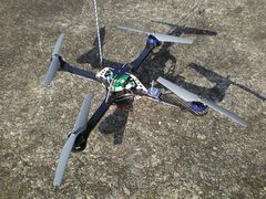
Booz is an extension of Paparazzi to VTOLs. At the current stage of the project, the system provides attitude stabilization, vertical guidance and automatic navigation. It is able to use simple Paparazzi flight plans ( only go instructions ) and uses Paparazzi telemetry and datalink, which means all the Paparazzi ground segment applications are available( plotter, settings, gcs, etc...)
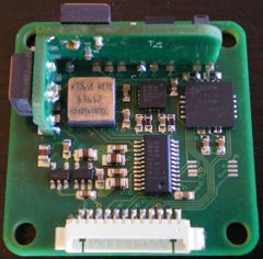
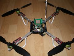
The current avionics consist in 3 boards
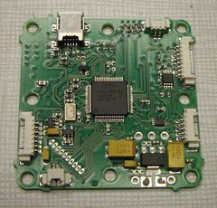
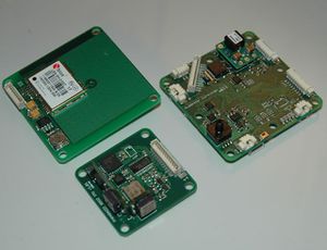
- The main board, comprising power supply, a LPC2148 and a barometer.
- The IMU board, comprising gyroscopes, accelerometers, magnetometers and a 16 bits ADC.
- The GPS board, using a LEA-5H by ublox.
Additional Booz boards:

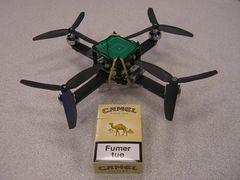
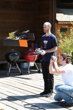
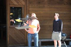
It flies on a variety of Quad-rotor platforms
and less common vehicles
Running a simulator
Booz features a simulator which can serve many purposes, from learning how to operate it to evaluating control or estimation algorithms.
BoozSimulator
Hardware
Motor controllers
Booz is able to handle a number of quadrotor specific brushless motor controllers.
more info in BoozMotorControllers
Power board
The power board allows to switch power on and off on your vehicle as well as to make a clean wiring by avoiding wired Y
more info in BoozPowerBoard
IMU
Booz has support for its custom designed IMU as well as for Cloudcap Crista IMU
more info in BoozIMU
Autopilot
Current version of Booz autopilot is based on a lpc2148
more info in BoozAutopilot
A new version of the autopilot, based on a STM32 is in development
more info in Lisa
Airframes
One nice thing about quadrotors is that the mechanics being extremely simple, they can be build with very little tools.
Booz mounting holes are compatible with asctec and mikrokopter frames
more info in BoozAirframes
Purchasing Hardware
There are now vendors offering Booz hardware, Please see the Get Hardware page for details.
Hardware Test
Booz comes with a number of simple test programs that you can use to validate a newly assembled board or learn how booz code works in case you want to extend it.
more info in BoozHardwareTest
Sensors Calibration
All our sensors needs to be calibrated in order to provide useful informations.
more info in BoozSensorsCalibration


