Difference between revisions of "Apogee/v1.00"
Jump to navigation
Jump to search
| Line 1: | Line 1: | ||
{| align=right | |||
<div style="float: right; width: | |- | ||
|<categorytree style="float:right; clear:right; margin-left:1ex; border: 1px solid gray; padding: 0.7ex;" mode=pages>Autopilots</categorytree> | |||
|} | |||
<div style="float: right; width: 65%"> | |||
[[Image:Apogee_v100_top.jpg|260px|Apogee v1.00 bottom side]] | |||
[[Image:Apogee_v100_bottom_1E.jpg|400px|Apogee v1.00 top side]] | |||
</div> | |||
__TOC__ | |||
= Overview = | |||
== Hardware Revision History == | == Hardware Revision History == | ||
Revision as of 04:03, 23 July 2013


Overview
Hardware Revision History
| Version # | Release Date | Release Notes |
|---|---|---|
| v1.00 | 07/2013 | Initial release of Apogee |
Features
- STMicroelectronics STM32F405 MCU based
- 9(6) DOF integrated IMU MPU-9150(6050) based
- 1 x Barometer/altimeter MPL3115A2 (I2C, MPU slave capability)
- 1 x MicroSD card slot, 4 bit SDIO interface (high speed data logging)
- 1 x USB : DFU mode (download) or USB storage (direct access to MicroSD card)
- 6 x Servo PWM outputs
- 1 x R/C receiver PPM frame input
- 1 x R/C receiver serial input with inverter (Futaba S.BUS, Spektrum, etc.)
- 3 x UART
- 2 x I2C bus
- 1 x SPI bus
- RTC with backup capacitor
- SWD(ARM download/debug interface)
- 4 x Auxiliary I/O (General Purpose and/or ADC and/or servo PWM)
- 5v / 1.5A switching power supply (input voltage range 5.5V min → 17.0v max)
- 3.3v / 1A linear regulator
- 1 x 5v / 500mA power switch
- 4 x status LEDs
- ?? grams (?? oz)
- 53 x 25mm (2.1" x 0.98"), shares the same external dimensions and mounting points as UmarimLite
- 4 layers PCB design
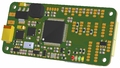
Apogee v1.00 3D bottom view
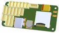
Apogee v1.00 3D top view


Pinout
Pins Name and Type are specified with respect to the Autopilot Board

Schematic
soon...
Examples of Airborne Equipment Electrical Connections
Small Aircraft Connection Diagram
soon...
Large Aircraft Connection Diagram
soon...
PCB
Gerber & Drill Files
Assembly
Components Layout
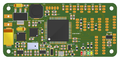
Apogee v1.00 bottom components Layout
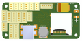
Apogee v1.00 top components Layout


Bill Of Material
PCB and assembled boards suppliers
Check availability on Get Hardware page
Mechanical Dimensions

